Here's a photograph of a board under test. It's about the size of the palm of your hand and is covered in logic clips for the logic analyzer and the converter, and with the oscilloscope probes. The multi-wire connector on the left goes to a debugging pod. Power and an RS-485 bus connection enters the board via the blue cable from behind. The firmware I wrote for this product is in a dialect of C, runs on a Microchip PIC16F1823 microcontroller unit (MCU), and has no operating system.

Logic Analyzer
A logic analyzer is a hardware device that allows you to make sense of one or more digital signals. The term digital here is important: the signals have to be logic voltage levels, for example 3.3 or 5 volts. Much more than that and your logic analyzer is not only not useful, it may actually be damaged. The signals have to be logic zero or one. The analyzer will interpret voltages below a threshold as a zero, voltages above another threshold as a one. That's all it knows how to do, zero or one, so analog signals that don't follow those rules will be misinterpreted. The signals have to change with a frequency no greater than the speed at which the hardware inside your logic analyzer can sample. The ability of the logic analyzer to recognize, capture, store, and display after the fact, digital events that occur faster than any human could possibly see them is the essential goodness of the tool. And this speed thing is important. It's the reason perfectly useful logic analyzers range in price from as little as US$150 to US$25,000 or more. The ability to capture higher frequency signals means more dollars.
I've used logic analyzers at the high end when someone else paid for them. But when it came to investing in one of my own, I bought a Saleae Logic, an eight-channel 24-megaHertz logic analyzer. I love it. At US$149, it's so ridiculously functional for its price, it'll pay for itself the first time you use it.

The Logic has a tiny aluminum electronics pod that is almost covered by my company's property sticker. It comes with a wiring harness that plugs into the pod, small logic clips that fit on the wires on the harness and then clip to the digital pins you want to look at, and a USB cable. You can see how small it is by comparing it to my little Swiss Army pen knife at the top of the photograph. All of this fits in a small zippered case that comes with the Logic.

The Logic depends on a computer (Windows, Mac, or Linux) with a fast USB port for power and to do the heavy lifting of its user interface (UI). Here it is connected to a small HP 110 Mini netbook that I carry around in one of my field cases that live in the trunk of my car. But Saleae makes it trivial to install the same software on any computer that is handy at a customer site.
Here's a Logic trace for a board that uses the Enhanced Universal Synchronous Asynchronous Receiver Transmitter (EUSART), also known as a serial port controller, on the PIC MCU to talk to an RS-485 bus transceiver chip. (Like all the photographs here, you can click on it to get access to larger versions.) Three digital signals go from the PIC to the transceiver: Receiver Output (RO) (receive or RX on the EUSART), Driver Input (DI) (transmit or TX), and Driver Enable (DE). You can see that I labeled the signal traces using the Logic UI.

RS-485 is a multi-drop half-duplex differential serial communications bus standard. Only one node on the bus can talk at a time. The DE signal tells the transceiver when it can drive an output signal onto the bus. This signal is explicitly controlled by code in my firmware, not by the EUSART controller. I wanted to verify that I was setting DE high before the EUSART began clocking the character out onto the bus, and then setting DE low after (but not too long after) the last data bit was clocked onto the bus.
You'll notice one of the great features of the Logic: it actually decodes the serial characters and tells me what they are (an ASCII 'B' in this case). This makes the Logic a kind of simple protocol analyzer as well. You can also see the two green timing flags the Logic UI provides that I moused around to have Logic calculate the time interval between the last bit of serial data going out on the bus and the DE signal being brought low: a completely comfortable 36.5 microseconds.
The Logic proved valuable in debugging two other issues with the RS-485 bus. When I first started using the RS-485 bus, I was getting garbage on the bus. The Logic told me that the characters I was outputting had framing errors. Thanks to the decode, I could also see that the characters being output onto the bus weren't even the right characters.

But the real clue was the fact that the DI line appeared to be idle low (zero) between successive characters when the correct idle state was high (one). RS-485 uses differential signaling over two wires that are by convention called A (negative or inverting) and B (positive or non-inverting). I had carefully followed the labeling on the board schematics, and verified that the schematics matched the data sheets for the RS-485 transceiver chip we were using. But the Logic suggested that I had A and B reversed. Some judicious Googling revealed that many transceiver manufacturers reverse the meaning of A and B from that of the RS-485 standard. Srsly? Reversing the wires fixed this problem.
Later, I noticed that I was occasionally getting a spurious character output onto the bus as my firmware started up. The character was always a hex 0xFF. I was sure I had some bug in my buffer handling.

But twenty seconds of looking at the Logic trace told me that this character was being output well before the bus driver in my firmware emitted its first character. In fact, it was being output before I even initialized the DE signal to it's correct state, one of the first things my firmware does. The problem was back in my hardware initialization code: I wasn't setting the DI pin to the correct initial value and in the correct order relative to initialization of the DE pin. The values of the not-yet-initialized pins just conspired to look like I was putting a 0xFF character onto the bus.
One of the boards I'm writing firmware for on this gig has a light sensor chip that the PIC MCU controls via an Inter-Integrated Circuit (I2C or more conventionally I2C) bus. I2C is a two-wire serial bus standard that is very commonly used to allow two chips on a board to communicate. (I2C is not, I repeat not, an interprocessor communications interface. But that is an article for another day.) It uses two digital signals, Serial Data (SDA) and Serial Clock (SCL).

In this first trace you can see the goodness of the Logic's decoder capability, telling me what the digital pulses on the SDA line really mean in an I2C context. In this example, my firmware is writing a value into a register in the light sensor chip. You can see that the Logic helpfully marks the beginning of I2C protocol sequences with green dots, and the end of the sequence with a red dot.

This trace is an example in which my firmware is reading a register in the light sensor chip. The decode tells me what the value read was. Of course, the best tool in the world can't help you if you're having a senior moment.

Initially my I2C state machine wasn't completing correctly, so my I2C handler was getting hung up. This Logic trace showed me that the light sensor chip was holding the I2C bus in it's none-idle (zero) state as if it thought it had something else to do. I knew my code was doing something bone-headed with the I2C communication with the light sensor. Things would have gone a lot faster had I noticed that the Logic I2C decoder wasn't displaying the helpful red dot showing that the I2C sequence on the bus had terminated correctly. It took a colleague sitting near me to remark "Are you sending an I2C NAK instead of an ACK at the end to terminate the sequence?" D'oh! Five minutes and one minor code change later, I had a working I2C handler.
Since I bought the Logic, Saleae introduced the sixteen-channel Logic16 for US$299. That same colleague bought one after seeing me use my Logic. After seeing his Logic16, I ordered one too. Tool envy: it's not pretty.
Oscilloscope
Back in the day when I was an undergraduate and wooly mammoths roamed the plains, I actually had to take a short course in how to use an oscilloscope. This, even though I was majoring in computer science, not computer engineering. This was when oscilloscopes were the size of a carry-on suitcase and logic analyzers were in more the realm of Star Trek instead of something a guy like me might actually own two of. The wisdom of my professors revealed itself as time passed and, yes, I came to own an oscilloscope too.
Although logic analyzers have replaced oscilloscopes for a lot of applications, oscopes are still vital tools for the embedded developer wherever analog signals crop up. As their name implies, oscopes are devices that allow you to see oscillating signals. More specifically: analog signals, which may vary continuously in time instead of being discreet lows or highs, which may vary in voltage from zero (or even negative) to something much higher than digital logic levels, or which are supposed to be digital but which are somehow not well behaved and hence misinterpreted by a logic analyzer.
The oscilloscope I was trained on eons ago was probably a mostly analog device. It may even have had vacuum tubes in it. Or maybe twigs and bark. But a modern digital storage oscilloscope (DSO) is a purely digital device that samples an analog signal and displays it continuously in real-time. Like logic analyzers, DSOs have a wide price range depending on sampling rate and capability. And like logic analyzers, very useful models are well within the budget of guys like me.

I own a Velleman PCSU1000, a two-channel 60-megaHertz DSO capable of handling analog signal levels up to 30 volts. I paid around US$350 for mine off Amazon.com, if you can believe it. Like the Saleae Logic, the PCSU100 depends on a laptop with a fast USB port (Windows only, alas) to store the digital samples and implement the user interface.

The PCSU1000 is about the size of a netbook. It's front panel accommodates two channels and an optional external trigger. The USB cable plugs in on the back.
One of the devices I wrote firmware for was a motion detector chip that has a two passive-infrared (PIR) sensors. The difference between the output of the two PIRs was expressed as an analog signal. The PIC read this analog signal using an analog-to-digital converter (ADC) built into the MCU.

Here is what the signal going into the PIC looked like as displayed by the PCSU1000. It's clearly not a digital signal: it's measured in millivolts, a signal level that a logic analyzer would probably interpret as a zero. Also, the duration of an entire event from the motion sensor is about a second, an eternity in the digital domain. Using the PCSU1000 to reveal the amplitude, shape, and duration of this waveform helped me configured the ADC on the PIC and understand its results once I had the code working.
Another task I had was to generate an analog output, in the form of a pulse width modulated (PWM) signal, to act as a kind of intelligent rheostat for lighting control. There were two phases to this output signal: the essentially digital PWM output from the MCU that my firmware generated, and the analog voltage going to the light fixture that a backend analog circuit amplified up to 10 volts.

Here is the PWM output generated by my firmware on the PIC MCU. This is a digital signal that the Logic could have easily interpreted as well. But the PSCU1000 allowed me to watch it in real-time as I changed the PWM duty cycle. This trace is a 20% duty cycle, meaning the signal is in the on-state for 20% of its total period. To an analog device, this looks like an analog voltage that is 20% of the maximum voltage, because the analog device effectively sees the integral of the voltage of the digital signal.

This is a 50% duty cycle. You can see the duration of the on-state has gotten longer.

And this is an 80% duty cycle.
But as cool as that is, here is the really useful thing: this is a movie of the PSU1000 displaying the output of the 10 volt amplifier circuit as my test firmware turns the voltage up and town by varying the PWM duty cycle of the digital signal from 0 to 100% and back again, just as if I were manually turning a wall-mounted dimmer switch up and down. The logic analyzer could never do this.

And because, as my colleague John Lowe says, the voltmeter never lies: here is my handy Radio Shack multimeter displaying the analog voltage at 100% duty cycle.
Logic-Level Serial-to-USB Converter
Actual RS-232 signal levels can be as high as 12 volts or more, and bits on an RS-232 signal wire are encoded as both positive and negative voltages. The serial output of a USART on your microprocessor or microcontroller is nothing like this. Instead, it uses logic-level signals ranging from 0 to something like 3.3 or 5 volts. The serial port on an MCU is frequently used for talking to some other chip on the board; in my case, an RS-485 transceiver chip. But sometimes it really pays to have a way to borrow the serial port for purposes of debugging. I use an FTDI Friend from Adafruit Industries to do this.

The FDTI Friend is a tiny circuit board smaller than your thumb that has on it a chip made by Future Technology Devices International that converts logic-level serial signals to a USB serial connection. I've confessed my love for FTDI before. When it comes to serial-to-USB conversion of any kind, I won't use anything else. Because everything else is crap.

I added a USB cable, some jumper wires, and a few logic clips, and I now have a device I can clip onto the serial port pins of a microprocessor or microcontroller under test, hook the USB cable onto a laptop, fire up my favorite terminal emulator like PuTTY or screen, and spy on what its serial port is saying. I do this. A lot.

Here is the output from some test firmware I wrote to continuously query the light sensor chip via I2C and dump its measurements in hex encoded in fractions of a lux to the serial port. I inserted the FTDI Friend between the PIC MCU and the RS-485 bus transceiver, clipping its leads right to the pins on the bus transceiver, which were larger and hence easier to use than those on the MCU.

Similarly, here is the output of some test firmware I wrote to query the motion sensor chip via the ADC and dump its measurements in hex encoded as a ten-bit value relative to a 5 volt reference voltage to the serial port.
The FTDI Friend is invaluable for stuff like this. It's around US$15 plus a few bucks for the logic clips and jumper wires.
If, like me, you do embedded development, or indeed any kind of development where you are running close to bare metal, you have to have tools that allow you to peer into that hidden world and see what's going on under the hood. And if, like me, you are self-employed, or indeed are employed at all, you have to know what your time is worth. Tools like the Saleae Logic analyzer, the Velleman PCSU1000 DSO, and the Adafruit FTDI Friend, have saved me countless hours of debugging and guesswork. You owe it to yourself as a professional to have the best tools you can afford.
Update (2012-10-27)
I have another little gadget similar to the FTDI Friend that I like even better. It's a USB to 3.3V/5VAuto Sensing Adapter that I bought right off Amazon.com. It's functionally equivalent to the FTDI Friend, but it's an integrated cable in which the FTDI chip is embedded inside the hood of the USB connector, which makes it even easier to use.

I didn't mention it in the original draft of this article because it took a bit of fabrication to build it. It came with a Molex-style connector on the end which I clipped off and replaced with jumper wires to which I could attach logic clips as shown here. If you are comfortable using a soldering iron, a heat gun, and shrink wrap, it only takes a few minutes to make one of these, and it will become an indispensable part of your embedded toolkit.
Update (2013-01-02)
Here's another little gadget that's useful if you deal with hardware with legacy RS232 interfaces. It's an USB 2.0 Serial RS-232 DB9 Mini Adapter from Amazon.com that's not much bigger than just a DB9 connector hood. It's perfect to convert boards that come with a female DB9 connector to their RS-232 serial port to serial USB. (If they come with a male DB9 connector you'll likely need a null modem adaptor too.)

You can see these in use in some of my articles on older BeagleBoards or the more recent Samsung ODROID reference platform. These are so useful that I've purchased several, and I just keep them screwed onto the boards even when the project is in storage. Or, for example, in the box with my Abatron BDI3000 JTAG debugging pod, which occasionally needs to be reconfigured or reflashed using a serial cable.
Update (2017-01-17)
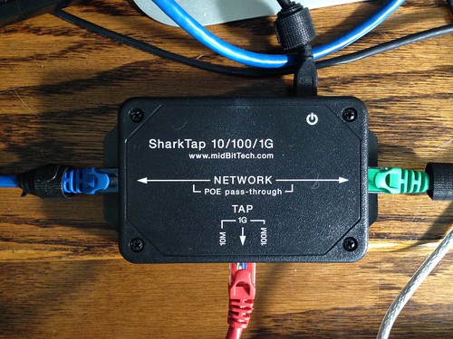
For those of you who spend time peering at Wireshark traces, this is the next gadget you'll want to buy: a SharkTap. Inside it's a Broadcom three-port (at least) gigabit Ethernet switch programmed to pass through everything between ports "blue" and "green", and mirror all that traffic to port "red". It's powered over USB. It's not cheap. But it might just be indispensable.