Test what you fly; fly what you test.
-- NASA aphorism
When you are responsible for maintaining a library of reusable software that contains components that deal with honest to goodness hardware peripherals, most or all of which don't exist on your build server, how do you unit test it? As an embedded developer with decades of experience under my ever lengthening belt, I deal with this quandary often. I've worked on projects that had a vast infrastructure to simulate the underlying hardware platform; maintaining that infrastructure was its own product development effort with its own unit testing issues. I've worked on projects that had part of a sizable test organization dedicated just to testing the software on development lab bench mules that were originally hardware prototypes. I've worked on projects that had no good long term approach. You probably have too.
One of the problems with any approach is the constant economic pressure not to maintain whatever test infrastructure existed once the project gets past one or two product releases and management turned its sights onto the next shiny new revenue producing thing. When it becomes time to fix some bugs and do a new release of the legacy product, the new engineer on the project - almost inevitably it is the new engineer on the project, sometimes a junior engineer tasked with proving themselves, in some group that might be euphemistically called something like "sustaining engineering" - is now faced with having to figure out all over again how to test their changes, on software they aren't familiar with.
I had to deal with this issue writ small when working on Diminuto, an open source (
LGPL) library of C functions that I have been developing over the span of more than a decade. It is my go-to systems programming toolkit. These days it’s hosted on
GitHub as
com-diag-diminuto, but it's been around long enough to have been maintained using several different version control systems. It started out in 2008 as a collection of supporting code for a tiny (hence the name) ARMv4
embedded project using Buildroot, with a stripped down Linux kernel, uClibc, BusyBox, and not much else. The project pre-dates the existence of the Raspberry Pi, and even the BeagleBoard.
Over time I kept expanding Diminuto as my needs grew, and porting it to new - and generally less expensive yet more powerful - platforms as they became available, as well as to new Linux releases as they arose. Eventually, all or parts of Diminuto ended up inside a handful of shipping products that I helped my clients develop. While I’ve done time in Python, wrote hundreds of thousands of lines of embedded C++ using the STL, fielded loads of Bash scripts, and even hacked JavaScript as the need arose, most of my paying gigs continue to be lower level systems work in C, writing device drivers, daemons, utilities, and glue code that holds all the higher level stuff together that's written by application and user interface developers. Diminuto also provides the infrastructure for a bunch of my other personal projects, most of which are also hosted on
GitHub.
(Added 2018-07-20) An issue with maintaining software libraries of reusable code intended for systems programming and embedded applications across multiple products is that the library is architecturally divorced from any one specific product. So while you may maintain a legacy product in a test lab for unit and functional testing, it may not be adequate to test all the features in a library because the product doesn't necessarily use all those features. So to really test a new library release, you might have to corral several otherwise unrelated test mules, if that's even possible. And even that might not be sufficient for acceptable test coverage. One reason this doesn't crop up more often - in my experience anyway - is that companies don't seem to see the value in such libraries, unless they come from somewhere else (e.g. open source). I suppose that's because, again, of the cost of maintaining them. That's another reason for Diminuto: I got tired of writing and debugging and testing and documenting the same proprietary closed source code over and over again (although, you know, paid by the hour) for different clients. Or, remarkably, sometimes for the same client, but that's a story for another time. And so, some or all of Diminuto now ships in several different products produced by completely unrelated organizations.
Diminuto has a bunch of modules, what I call
features, that are designed to work together.
Some features are not much more than preprocessor macros, for example:
- Critical Section (scoped POSIX thread mutex serialization);
- Coherent Section (scoped acquire/release memory barriers);
- Serialized Section (scoped spin locks); and
- Uninterruptible Section (scoped blocked signals).
Some provide simpler interfaces to inherently complicated stuff:
- IPC4 and
- IPC6 (IPv4 and IPv6 sockets); and
- Mux (multiplexing using the select(2) system call).
Some provide convenience interfaces that combine several operations into a single function call, sometimes atomically to make them thread safe:
- I2C (I2C bus);
- Log (logging API that works in kernel space or in user space, and which automatically directs log messages to the system log for daemons, or to standard error for applications);
- Pin (general purpose I/O using the /sys file system GPIO interface);
- Serial (serial port configuration).
Some implement interfaces that are more consistent and mutually interoperable than the native POSIX and Linux capabilities:
- Frequency,
- Time,
- Delay, and
- Timer (the usual time-related stuff but all using the same units of time).
Some implement functionality that is a bit complex in and of itself:
- Modulator (software pulse width modulation or PWM using POSIX interval timers);
- Controller (proportional/integral/derivative or PID controller);
- Shaper (traffic shaping using a virtual scheduler); and
- Tree (red-black tree).
Some are just useful to have:
- Phex, pronounced "fex" (print non-printable characters); and
- Dump (print a formatted dump of selected memory).
Having this collection of documented, pre-tested, reliable functions that handle the heavy lifting of the POSIX and Linux APIs that I routinely am called upon to use means I can rapidly toss together a usable working piece of C code without having to worry about whether I did the conversion between microseconds and nanoseconds for two different POSIX calls correctly.
Virtually all of the Diminuto features have
unit tests that verify the correctness of the implementation. These unit tests are part of the Diminuto repository, and like the library itself, I would expect them to build and run on any modern Linux distribution on any processor architecture.
I'm a big believer in unit tests. But some of these features, like Pin, Serial, Modulator, and Controller, can only really be adequately tested using
functional tests on actual peripheral hardware. Over the years, to test these features, I’ve built a series of
hardware test fixtures. These range from simple custom wired connectors, to breadboards with ICs on them. When I work on these features, I pull the appropriate fixture out of a box, hook it up to the system under test (typically a Raspberry Pi), and run the functional test.
Why is this important? Because I want to know my generically-useful but hardware-related features work before I (or anyone using my library) deploy them in an actual product development effort. And if for some reason they don’t work in the project, I want to be able to back up and use my functional tests to verify basic sanity, and to help me see where the problem might actually be. Even if the bug turns out to be in my code, the functional tests at least help me determine what does work and indict what doesn’t work. The functional tests also serve as a living example of how I intend the Diminuto features to be used.
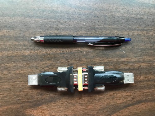
Here are a couple of CableMax USB-to-serial adapters, one with a hand-wired loopback, the other with a commercial loopback adapter. These make use of an FTDI USB-to-serial chip, which is pretty much the only brand I use these days for this type of device.
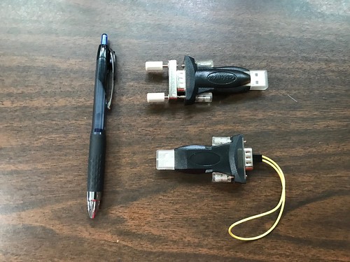
I use these to test the Serial feature and its ability to set baud rate, data bits, and stop bits using the
lbktest functional test.
Here is a NaviSys GR-701W USB GPS dongle that supports one pulse per second (1PPS) signaling using the data carrier detect (DCD) modem control line.
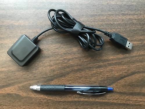
I use it to test the Serial feature DCD support by reading NMEA sentences from the GPS receiver using the
dcdtest functional test. As fringe as it may seem, I have several other projects, like
com-diag-hazer and its own dependents, that rely specifically on this feature. It pays to verify its functionality before any regressions creep outside of Diminuto proper. Which is really the point of all the functional and unit tests.
Here are more two CableMax USB-to-serial adapters connected back to back with a null modem adapter in between.
I also use these to test the Serial feature, either between computers or even on the same computer using two USB ports, using Diminuto's
serialtool utility.
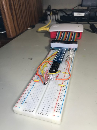
Here is what my latest functional test breadboard looks like.
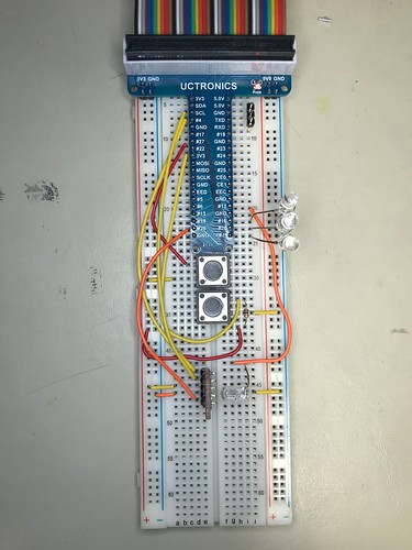
It consists of a
Uctronics expansion board that connects the breadboard to the Raspberry Pi via a ribbon cable; four LEDs with built in resistors; two momentary contact buttons, one active high, the other active low with a pull up resistor; and an
Avago APDS9301 ambient light sensor with an I
2C interface. I also bring out the pins to the hardware console port on the Raspberry Pi.
The
pintest functional test, based on the Diminuto's
pintool utility, uses Mux and Pin to read the buttons and to write patterns to the LEDs. Pin, Mux, and the underlying Raspberry Pi GPIO controller, supports multiplexing GPIO pins using
select(2).
The
pwmrheostat functional test uses Pin and Modulator to control as many as four LEDs concurrently, all at different brightness levels.
The
luxrheostat functional test uses Pin, Mux, Modulator, and I2C to control a single LED pointed at the ambient light sensor, turning the LED brightness up and down, while reading the light level.
The
luxcontroller (formerly
pidtest) functional test uses Modulator, Mux, Pin, and I2C to control the brightness of an LED and read its intensity on an ambient light sensor, and Controller to maintain a specified light level as the background illumination changes.
(I am in the process of adding a
TI ADS1115 analog to digital converter or ADC, also with an I
2C interface, to this breadboard to extend the testing of the Modulator software PWM feature and the Controller PID feature. I have a first cut at a
adcrheostat and
adccontroller functional tests.)
Here is a FTDI TTL-232R-3V3 USB-to-serial adapter that works with 3.3 volt logic-level signals, with logic clips at the end of the signal wires.
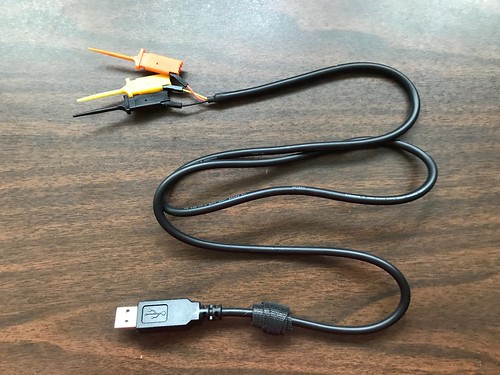
I use this to further test the Serial feature using the Raspberry Pi hardware console port that is accessible via the breadboard.
These test fixtures are pretty simple stuff. But they allow me to exercise the hardware-related features of Diminuto such that I have high confidence that I haven't done something boneheaded. When I'm not using them, these fixtures go back into the box and go up on the shelf.
When I'm thinking of adding another hardware-centric feature to Diminuto, one of the first things I decide is how I am going to test it: if I can do so with an existing fixture; if I need to add to an existing feature like the breadboard; if I need to build a new fixture; and how much that's going to cost. Sometimes I decide the cost isn't worth it, and forgo developing the feature in Diminuto at all, leaving it to a future client to pay for and maintain if its needed. Or maybe I just wait for technology to catch up.
Test what you ship; ship what you test.
-- Chip Overclock aphorism
Updated 2018-07-25
Here's a photograph of the breadboard after I added the ADC. It's getting complicated enough that I probably should actually generate an official schematic just for my own records if nothing else.
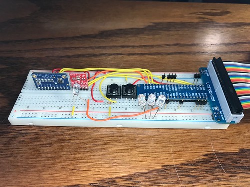
The
adcrheostat and
adccontroller functional tests now use Pin and Modulator to do PWM on a GPIO pin, and I2C to read the voltage on the pin from the ADC (the tiny blue board). The latter test uses Controller to implement a PID controller that strives to maintain a specified voltage. These tests are a minor variation on how
luxrheostat and
luxcontroller use instead an LED and an ambient light sensor (the tiny red board).
Updated 2021-03-23
The
gpstool utility in my Hazer project (
com-diag-hazer) depends mightily on Diminuto for its infrastructure. Testing some of the Hazer features finally got complicated enough that I built a dedicated test fixture for that project too.
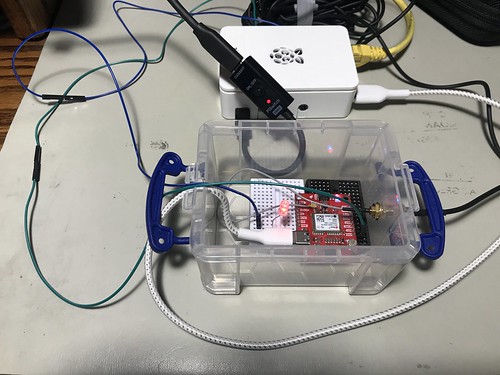
While gpstool supports a wide variety of GPS/GNSS receivers, the one I chose for the test fixture is a u-blox NEO M8N device, which can simultaneous receive and process transmissions from the satellite constellations of the U.S. GPS (a.k.a. NAVSTAR) system, the Russian GLONASS system, the European Galileo system, and the Chinese BeiDou 2 (a.k.a. COMPASS) system. This tests more code paths in the underlying Hazer library and in gpstool.
The M8N is powered by a USB C connection to a dedicated Raspberry Pi 4B running Raspberry Pi OS, a Debian-based version of GNU/Linux. The USB connection is also the communications channel between the Pi and the M8N. The Pi runs headless; when necessary, I ssh into it from my desktop Mac and use the command line interface.
You can see the SMA RF connector emerge from the container where it connects to the coaxial cable of the multi-band GNSS antenna used by the M8N.
The green wire connects the 1PPS ("one pulse per second") signal from the M8N to a General Purpose Input/Output (GPIO) pin on the Raspberry Pi. 1PPS is a standard precision timing signal derived from the GNSS solution by the receiver (although not all of them export it, and when they do, the mechanism varies). I make use of 1PPS in all of my GNSS-disciplined NTP micro servers that I've written about previously (including the one that incorporates a chip-scale cesium atomic clock). When gpstool is configured to monitor the 1PPS signal, it uses Diminuto's GPIO feature to interrogate the input GPIO pin using the select(2) system call inside a dedicated POSIX thread.
The blue wire connects an second, output, GPIO pin on the Raspberry Pi to an LED in the little container where the M8N is mounted. When gpstool monitors 1PPS, it can be configured for the thread to strobe the second GPIO pin to follow the 1PPS signal. This is not just a test of Hazer and gpstool, but a test of Diminuto's GPIO feature as well.