The Global Positional System (GPS) - or, more generally, all Global Navigation Satellite Systems (GNSS), which includes not just the U.S. system but those of Russia, the European Union, and China, as well as the non-global systems of Japan and India - uses differences in time and multilateration to provide solutions in the problem domains of Positioning, Navigation, and Timing (PNT). Because the time stamps generated by GNSS satellites cannot be perfectly synchronized and syntonized, the positioning accuracy of such systems in typical applications is at best within meters or even tens of meters. As remarkably useful as GPS is, it is not horse shoes and hand grenades close, but more like cricket and cruise missiles close. This is one of the reasons why GPS cannot be used alone for navigation in autonomous vehicles, and why your in-dash navigation display takes a few moments to realize you have exited off the highway onto an access road."All development is fractally iterative, whether you want it to be or not."
- Me (Often)
Differential GPS - or, again more generally, Differential GNSS - takes advantage of the fact that the sources of error (typically jitter) in the received satellite signals are uncorrelated with one another. Which is to say: random, or at least not systemic. So if a GNSS receiver is stationary, it can take advantage of its fixed location to compare each successive solution with either its own predetermined location, or with its own long term weighted average positioning solution. In the latter technique, called Real Time Kinematics (RTK), the receiver's position solution can become more and more accurate over time. Depending on a number of factors like antenna placement and how many satellites it can see overhead at a time, a stationary receiver, or the Base in DGNSS parlance, can achieve an accuracy down to centimeters or better.
This sounds great, but it doesn't help the mobile receiver, or Rover. Except if the Rover is close enough to the Base - in the same neighborhood - the two receivers will see the same satellites overhead, and therefore suffer similar degradation in the signals. The Base can transmit its corrections to one or more Rovers, and each mobile Rover can then potentially achieve a similar level of accuracy.
But how DGNSS works isn't what this article is about.
DGNSS products have been around for decades, costing on the order of thousands of dollars. Late in 2018, u-blox, the well known Swiss-based manufacturer of excellent (in my professional experience) PNT solutions, introduced their ninth-generation of GNSS receiver chips, the ZED-F9. This family of high-precision GNSS chips support DGNSS RTK directly, in the form of messaging conforming to the Radio Technical Commission for Maritime Services (RTCM) Special Committee (SC) 104 standard. This brings a DGNSS capability down to a price range of hundreds of dollars, potentially affordable to hobbyists, enthusiasts, experimenters, and consumers of applications like non-military drones and remotely piloted or autonomous vehicles.

Affordable, in fact, to PNT enthusiasts like me.
This article is about the iterations I went through to establish my own permanent Differential GNSS base station, and to cobble together a Rover that I could use in the field for precision geolocation. I leveraged and significantly modified my existing Hazer GPS software (com-diag-hazer on GitHub), but most of that was just bookkeeping and glue code; the firmware in the u-blox chip does all of the heavy lifting, including sending and receiving the RTCM messages. I make use of old stuff I had at hand at the Palatial Overclock Estate, new but mundane consumer-level stuff I bought off the shelf at my local office supply and hardware stores, and some special purpose stuff I bought online.
This is an approach to building prototypes I call improvisational engineering and what some folks refer to as Macgyvering. But all development is iterative, even building proof-of-concepts.
I code-named this project Tumbleweed.
Iteration 1
I have been using u-blox PNT solutions for years professionally. And the National Center for Atmospheric Research (NCAR) in Boulder Colorado had an R&D group decades ago when I worked there that was using DGNSS that was good enough that they could measure the swinging of instrument packages tethered to high altitude weather balloons. So when I first read about the ZED-F9 on the Time Nuts mailing list, my ears perked up. It took just a little Google Fu to discover that the start-up Ardusimple was selling a relatively inexpensive board, the simpleRTK2B, that used the ZED-F9P chip. The board included the capability to incorporate any one of a variety of tiny Digi XBee radios for the Base to communicate with one or more Rovers. In the spring of 2019, I wielded my credit card.

This shows the bare simpleRTK2B board. You can plainly see the u-blox ZED-F9P chip on the board. At the top of the board is a socket for an Xbee radio, and a micro-USB connection to the serial port on the radio. At the bottom left is an SMA RF connector for the multi-band GNSS antenna. At the bottom right is a micro-USB connection to the ZED-F9P serial port.
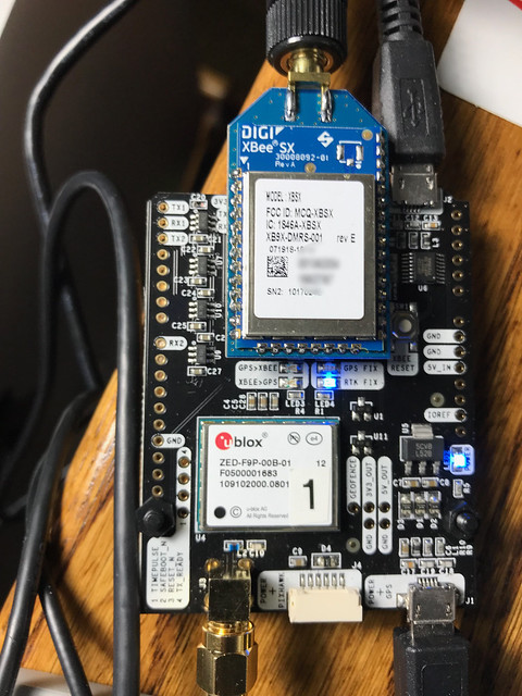
Here is the same board with a socketed 900MHz Xbee radio with an antenna attached to its own SMA connector.
Two simpleRTK2B boards connected to a couple of Raspberry Pi Single Board Computers (SBCs) running Raspbian Linux (based on Debian) made it possible for me to adapt and test my Hazer software, to figure out how to configure the ZED-F9P chips for Base and Rover mode, and to verify that the chips did indeed exchange RTCM messages. I ran the Base and the Rover initially in my home office, the GNSS antennas sitting in my office window. But for the Base to converge to an accurate solution - or, at least the accuracy I was shooting for, which I arbitrarily set at 2.5cm or about 1 inch - antenna placement is crucial. I was going to have to move the Base, or at least its antenna, outside in the long term.

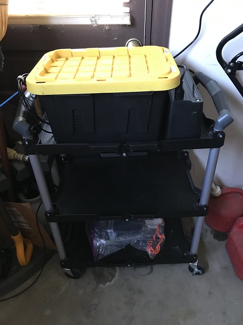
This is my first "field" test. The simpleRTK2B boards are inside a couple of plastic organization boxes from the local office supply store, just to keep dust and weather and maybe the errant finger off of exposed PCBs. I used a Dremel tool to make holes for the RF and USB connections. The two Raspberry Pis were inside standard Pi cases. Trying to emulate how I thought things would work in the long run, I used my MacBook to SSH through my home WiFi network into the Pi being used as the Base, and used an old Asus ChromeBook as a serial console to the Rover as I expected to in the field. You can see the multi-band GNSS antennas for the Base and the Rover set up on tripods to the right of my driveway. Note that the 900MHz antennas that connected the Base to the Rover are just inches apart on the cart. Everything was powered from mains; you can see the power cord snaking off to the left.
With this set up, the Base was able at times to see as many as thirty-two GNSS satellites - the limit of the RF section of the receiver - in some combination of the U.S., Russian, European, and Chinese systems. It was able to achieve my target accuracy (according to, it must be said, its own estimates) in just a few hours of running. The next step was to move the Base and the Rover further apart.
Iteration 2
I purchased a couple of cheap but remarkably sturdy plastic tubs with lids from my local hardware store, one for the Base and one for the Rover. I used my Dremel tool to make holes for RF, serial, and power cables.
The Base stayed safely tucked into a corner of my garage out of the weather. It was powered off the mains, but with a Uninterruptible Power Supply (UPS), visible to the right of the tub. The coaxial cable to the antenna, visible on the floor on the left, ran underneath the garage door.
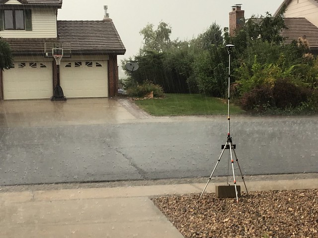
The Base antenna was at the edge of my front yard on an old camera tripod. Fortunately the survey antenna was rated for water resistance. In this photograph it is surviving a hail storm.
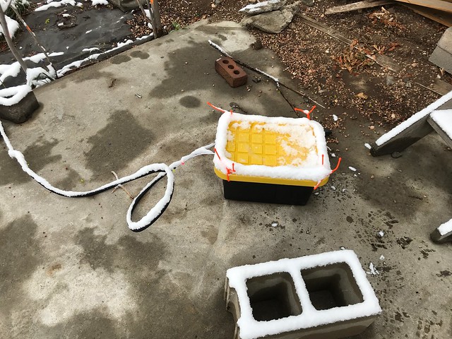
The Rover was in my back yard. The tub holding all the electronics plus a big lithium battery pack was situated on an old concrete slab. Here it is surviving an early spring snow.

You can see the Rover antenna on another old camera tripod, during the same snow storm. The multi-band antenna has an inch or two of snow on top of it. You can see the 900MHz antenna fastened to the tripod handle just to the left.
This iteration taught me that while 900MHz radios may have a theoretical range of several kilometers, they are strictly line of sight devices. They may work for communication between, for example, a Base on the ground and a Rover on a drone in the sky, but they didn't work for me with my two-story suburban house in the way. Since it was my goal to have my Base at home while testing the Rover at nearby U.S. National Geodetic Survey (NGS) markers in the neighborhood, I would have to solve this problem.
Iteration 3
I replaced the Xbee 900MHz radios with Xbee LTE-M radios made specifically for embedded Internet of Things (IoT) applications. The advantage of these radios is they have the same pin-out and form factor of the 900MHz radios and would have worked on the simpleRTK2B boards. I used data-only AT&T SIMs intended expressly for IoT machine-to-machine (M2M) applications like this one.
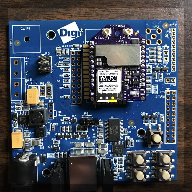
Here you can see one of the LTE-M radios socketed on a Digi evaluation board that I used to play with it independently of the simpleRTK2B board.
What I learned is that in configuring an LTE-M radio for UDP connectivity, I had to provide it with a fixed IP address of the destination, not a domain name. (The configuration tool allowed a domain name for TCP connections, probably because the domain name only needs to be resolved once per connection.) My home network doesn't have a fixed IP address. I use a Dynamic Domain Name System (DDNS) provider that conspires with my access point router to map my fixed domain name to the variable IP address supplied by my internet service provider via DHCP every time my access point router connects to the Internet.
I couldn't find a way around this. I'd like to be proven wrong, since these devices were not cheap. I talk about why I use UDP for PNT applications like this in the article Better Never Than Late.
Update (2021-04-30): A year later I've revisited these devices and am using them successfully with UDP in a different project. While what I said here was true, it was only true when using the devices in their "API" mode, which was necessary at the time for the project I am describing to delineate datagrams when using binary protocols like RTK and when serially connecting the radio directly to a GNSS device. Now I'm using them in a different application in "transparent" mode with UDP, delineating datagrams containing JSON messages using a newline character, and in this mode they resolve my domain name just fine. I'm using SIMs for the AT&T "One Rate" LTE-M plan.
Iteration 4
About this time I had found some nice 3D printed cases specifically for the simpleRTK2B boards on eBay (I don't find them now). So I dispensed with the clear plastic pencil boxes from the office supply store. That was the simplest part of this iteration.
Fortunately, I already had a Verizon USB-attached LTE modem that I had used in other projects (in fact, in the project I discussed in Better Never Than Late). I decided to try using that for the network connection of the mobile Rover to the fixed Base.
But the LTE modem enumerates as a USB Ethernet dongle, providing an IP address to the Raspberry Pi via an embedded DHCP server once it connects to the Verizon mobile network. That meant completely rethinking the configuration of ZED-F9P chips in both the Base and the Rover, so that the RTCM messages were not routed out to the on-board radio (which was removed now), but back up through the USB connection to the Raspberry Pi.
This required a substantial amount of work in the Hazer software to recognize and route the incoming RTCM messages from the ZED-F9P on the Base, out to the Internet via my home network service provider, to the Verizon mobile network, to the LTE modem, and finally to the Raspberry Pi in the Rover.
But like the Base on the DDNS-serviced home network, the Rover also does not have a fixed IP address on the Verizon network. So I had to add a third component to the Base and Rover: the Router (not related to my access point router for my home network).
In this architecture, the Base and Router sit on my home network, and can in fact run on the same Raspberry Pi. The Base sends RTCM corrections to the Router. The Rover in the field connects to the Router via my home network's fixed DDNS domain name, which gets translated into whatever IP address my internet service provider assigns my home network. The Rover sends periodic keep-alive messages to the Router, and Router forwards the RTCM corrections to the Rover. As long as the Rover sends keep-alive, it keeps getting RTCM corrections.
I was also concerned about the power draw of both the LTE modem and the simpleRTK2B board from the Raspberry Pi. So I added a powered USB hub to the Rover, which would itself be powered separately from the ginormous lithium battery pack that was in the Rover plastic tub.
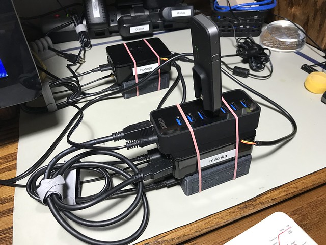
Here you can see the Base (in the background) with its Raspberry Pi and simpleRTK2B in its 3D printed plastic case, and the Rover (in the foreground) with its LTE modem, USB hub, Raspberry Pi, serial console cable, and simpleRTK2B with case, all stacked up for testing on my lab bench.
Despite the photographs above, some of my test days had sunny, hot weather.
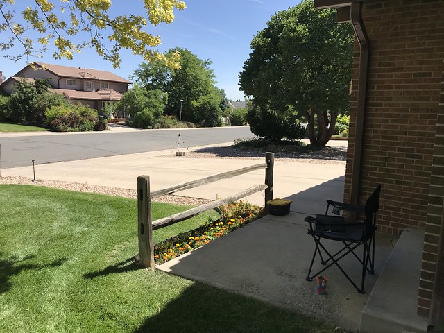
Here, you can see the Rover tub and its antenna to the left of my driveway, and the antenna for the Base to the right of my driveway (the Base still tucked safely away in the garage). I was situated in the folding camping chair in the shade of my front porch with a cool drink.

In this iteration, I learned that the PLA plastic used in hobbiest-grade 3D printers have a glass transition temperature (i.e. melting point) of 140F (60C). And that 140F is easily achievable on a hot summer day and when you have a busy Raspberry Pi bundled up against the 3D printed simpleRTK2B case. Both the Raspberry Pi and the simpleRTK2B boards survived this ordeal, but the 3D printed case for the simpleRTK2B in the Rover did not. Concerned about damage to what was now a significant investment of time and money, I realized I'd have to solve this problem.
Iteration 5
Step one to solving the heating problem was to put both Raspberry Pi 3b+ SBCs into cases that included a fan. Step two was use velcro to mount the Raspberry Pis in their new cases, the simpleRTK2B in their 3D printed cases, and the powered USB hubs (which by now had been added to the Base as well as the Rover), side-by-side on a sheet of Lexan, with some air space between them. Step three was to drill some extra ventilation holes in the tubs near where the Raspberry Pi would be located.

Step four was to add a USB-powered exhaust fan to both the Base and the Router tubs to keep air flowing. These USB fans were powered from the USB hubs in each tub.

This is the inside of the Base tub. On the left you can see, top to bottom: the USB hub with an LTE modem (for testing, not needed in production, since the Base sits on my home WiFi network); the simpleRTK2B in its 3D printed case; and the Raspberry Pi in its case with its own fan. Top right, you can see the USB fan. In the middle, you can see the battery powered thermometer with a min/max function I added to both tubs so that I could keep track of how hot things were getting. (There's also a command line tool you can use on the Raspberry Pi to access its own internal temperature sensor; a script to access that sensor is included in Hazer.)
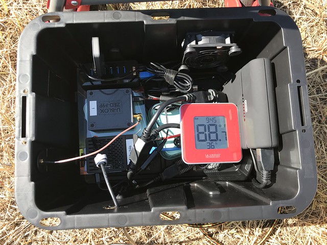
Similarly, this is the inside of the Rover tub. In addition to all the same stuff as above, there is the ginormous lithium battery pack on the right.

I got the bright idea of looking up nearby NGS markers on their NGS Data Explorer web site and using them to test against. For example, above is marker KK1446, a.k.a. "Dover", established in 1977. It set the positioning standard against which the housing development all around it, and the cell tower right next to it, were established.
I continue to use such survey markers for testing even though I eventually learned that the latitude/longitude produced by the various GNSS systems is not the same as the latitude/longitude used by the NGS. That's because the two systems use different datums: abstract models of the shape of the Earth. They cannot be directly compared.
Oh no! Not another learning experience! (But more on that in a later article.)

This is the Rover that I used for actual field testing at the survey markers. The Asus Chromebook I used as a serial console is under the silver and black sunshade. That's sitting on top of the yellow and black Rover tub. The GNSS antenna is in the background left, right over the survey marker. The entire affair is large and unwieldy enough that I carted it to and from my car with a folding hand truck.
It was this iteration - which included testing at several different survey markers, some of which were right up against busy roads - that convinced me that simplifying and reducing the amount of gear I had to tote around for the Rover would be a good thing.
Iteration 6
Antenna placement for the base station is crucial. All my testing that led to a successful position fix that converged to my desired level of accuracy within a reasonable amount of time (hours) were done placing the Base antenna outside. My goal then was to have a multi-band GNSS survey antenna permanently mounted outside but with the Base indoors.
My plan was to mount the multi-band GNSS survey antenna on a mast on my chimney, run the coax though an existing path through the outside wall used decades ago by the previous owners of my house for an antenna for broadcast television (seriously, that used to be a thing, kids).

I went so far as to remove the old television coaxial cable and run the GNSS coax through the existing hole in the wall and attach it to a grounded lightning arrestor.
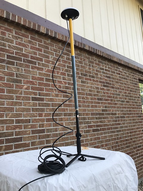
I temporarily attached the antenna I was going to mount outside to the other end of the lightning arrestor. That tripod that it is on, also visible in other photographs, is actually a inexpensive selfie-stick, with some extension poles attached to it. I attached a spare ZED-F9P to the other end of the coax inside the house and verified that I was able to receive GNSS signals.
I had several email exchanges with a professional consumer antenna and satellite dish installer about installing the GNSS antenna. Because of the orientation of my house on my lot, and the nature of my roof, the task got more and more complicated - not to mention expensive. I spent a lot of time looking for alternatives. Eventually, I found a great one.
Iteration 7
For some time now, in the timeline of this project, I had been using the Ardusimple simpleRTK2B boards because they were equipped with the u-blox ZED-F9P chip. But ultimately I ended up not using any of the additional features of the board. I began using my Google Fu to find an alternative. I was delighted to find that since I had started working on Tumbleweed, one of my favorite maker parts suppliers, SparkFun Electronics, just up the road from me in Boulder, had started marketing a smaller, simpler, less-expensive GPS-RTK2 board that incorporated the ZED-F9P. I purchased one of the boards to evaluate, and eventually, once I discovered that my software worked flawlessly on the GPS-RTK2 with absolutely no changes, I purchased a second one.

Here are the two GPS-RTK2 boards on my lab bench. Both are once again encapsulated in little plastic boxes from the local office supply store, modified with a Dremel tool to provide holes for the USB and RF cables. The board on the left is connected to a multi-band GNSS antenna off screen in my office window. The board on the right is connected to a multi-band GNSS helical antenna.
I made the decision to move to the GPS-RTK2 boards for my "production" Base and Rover. (I'm still using the Ardusimple simpleRTK2B boards for testing and other projects.)
Iteration 8
Part - maybe the major part - of any project is its engineering economics: deciding where and how to best spend a limited budget of both money and time. The idea of putting a GNSS antenna on the roof of my home was looking more and more like a non-starter, even though its location would be ideal in terms of its view of the sky, where bigger is better.
One day while in the kitchen (probably making a sandwich), I glanced up and realized that the skylight above my head was near the peak of the roof of that part of the house. An antenna in the skylight wouldn't have a completely unobstructed view of the sky, but it would be close. And it would be inside, protected from the weather, and relatively easily connected to the Base.
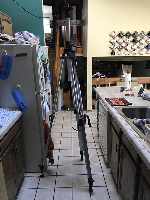
Conveniently, Mrs. Overclock (a.k.a. Dr. Overclock, Medicine Woman) was out of town at the time. I set up a tripod in the kitchen underneath the skylight.

I mounted a couple of extension poles to the tripod and at the top put the survey antenna. I slowly adjusted the center post on the tripod until the antenna was right against the plexiglass of the skylight. I attached the Base to the antenna and let it conduct its survey. At its peak, the ZED-F9P in the Base was able to see thirty-two satellites, the limit of the RF stage of the receiver. In a few hours it had achieved my target level of accuracy.
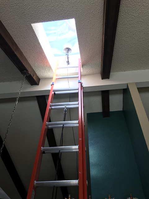
A few days later, Mrs. Overclock returned home, and after some discussion (we haven't been married for thirty-six years for no reason) she agreed to let me permanently place a gimbaled mount, intended for a security camera, in the skylight. I attached the survey antenna to it, and ran the coax over the low kitchen wall into a conveniently located corner of the living room, tucked away between the wall and an existing piece of furniture.

I used a stylish little end table from a local speciality retailer to hold a Raspberry Pi and one of my new GPS-RTK2 boards. This was my new permanent Base. It connects via WiFi to my home network.

Some time ago, I had separated the Base and the Router software functions onto two separate Raspberry Pis. (They had always been two separate programs in Hazer, so this was easy.) This is the Router, hidden inside the A/V cabinet in the family room, connecting directly to my access point router via a CAT5 cable.

The Base transmits its RTCM correction messages to the Router, and the Router forwards them to any and all registered Rovers.
My current thinking is that this is the final incarnation of the Base and the Router.
Iteration 9
There are a slew of Linux systems that run 24x7 at the Palatial Overclock Estate (POE) in a western suburb of Denver. Ten of them are Raspberry Pis, all but one of them running headless. Three of the Linux systems are Intel boxes I use as servers and development systems, also running headless. But none of them are laptops. I do occasionally run Ubuntu Linux in a VM on my one Windows laptop (because several proprietary embedded software tools I use at clients from time to time only run under Windows). But I have often felt that having a Linux laptop would be a useful thing; I've just never needed it badly enough to warrant spending the money, even on an inexpensive laptop.

It occurred to me that somewhere in the bowels of the basement of the POE - imagine if you will the scene at the end of the movie Citizen Kane, or the homage to that scene at the end of Raiders of the Lost Ark - I had - not a sled named "Rosebud", nor the Ark of the Covenant - but an ancient HP Mini 110 netbook, with an equally ancient version of Windows on it. These small laptops ran a 32-bit Intel Atom i686-class processor and, even when they were new, they were, as my friend The Deacon described them, "dirt cheap and dead slow", so underpowered that, as cheap as they were, they failed in the marketplace. Their niche was replaced for the most part by smartphones, tablets, Chromebooks, and Moore's Law. I wondered if I could scare up a version of Linux that would run on the Mini and resurrect it as a useful piece of kit.

A few hours later I had the Mini running Mint, a stripped down Debian-based distribution of Linux. Here you can see it configured as a Rover: running my Hazer software, connected to the Internet using the Verizon LTE modem, and using one of my Ardusimple simpleRTK2B boards, geolocating like a boss.
I was tempted to call this my production Rover. But the success of this inspired me to take one more step, one that would keep the Rover running on a Raspberry Pi, my SBC of choice because its ARM processor was similar to what I would expect to be used in a real product.
Iteration 10
I had been aware of Pi-Top, and especially their Pi-Top [3], for some time. The Pi-Top [3] is, in the words of the company, a "maker's laptop", intended primarily for use by STEM students, hobbyists, and maker enthusiasts. In other words, people like me.
But the [3] isn't really a laptop; it's a laptop shell. There's no main processor inside. But there is slot into which you can plug a Raspberry Pi 3B+ and have access to the Pi's various ports and pins. The result won't win any competitions with laptops like my MacBook Pro or my Lenovo ThinkPad. But it has something those devices don't have: space.
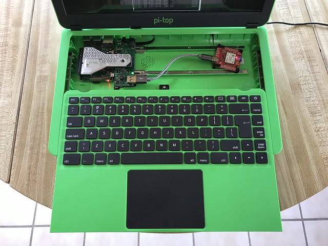
Sliding the entire keyboard facia forward reveals the Raspberry Pi 3B+, hidden underneath the silver heat sink and system connector on the far left. Just to the right of the Pi is the glue board or Hub that connects the Pi to the display, keyboard, trackpad, and internal battery of the [3]. And connected to the convenient USB port on the glue board, held in place magnetically to the built-in project rail, is one of my GPS-RTK2 boards with its ZED-F9P chip.

I drilled a hole in the rear of the [3] and mounted the SMA connector to the GPS-RTK2 for the GNSS antenna. I added the right angle swivel connector to reduce the stress on the plastic shell.
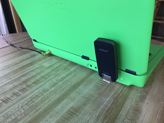
The Verizon LTE modem now lives at the rear of of the [3], where the Pi's other USB ports and Ethernet port are located.
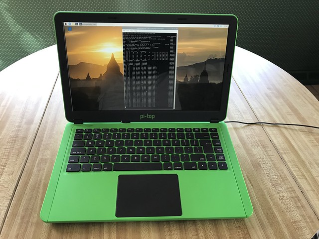
After some experimentation, I chose not to use the native pi-topOS Linux, but instead run the same version of Raspbian Linux I ran on the earlier Rover. It works just fine.

Here is my latest incarnation of the Rover, running on its internal battery, attached to the multi-band antenna, and connected to the Internet via LTE. It is far simpler, lighter, and less cumbersome than its predecessor.
I am just now testing this new Rover outside the house. I still have a few things to work out (a better sunshade so I can see the display on a typical brilliantly sunny day in Colorado). And I am somewhat delayed by a combination of nine inches of late April snow and a pandemic.
But I'm beginning to think there won't be another iteration.
Update (2020-05-04)
The backlighting on the Pi-Top [3] display failed during Rover testing. I briefly fell back to using the HP Mini 110 until an extremely helpful email reply arrived from a tech support engineer at CEED (the company that make the Pi-Tops). It walked me through disassembling the Hub and making sure the ribbon cables from the display were firmly seated in the connectors on the backside of the board. About thirty minutes of careful work later, I was up and running on the [3] again.
I used that effort as an excuse to upgrade from the Polaris release to the Sirius release of pi-topOS. I had not found Polaris (the version that came with the [3] that I bought) stable, and had reverted to running with straight Raspbian, the standard Linux/GNU distribution for the Raspberry Pi, which worked fine. (Raspbian is based on Debian Linux, and both Polaris and Sirius are in turn based on Raspbian.) The very recent Sirius release seems much improved over Polaris; since my software worked on it (subject to the necessary additions to the /lib/udev/rules.d directory and to the /etc/hosts and /etc/services files in support of Hazer), my current plan is to stick with it.
A useful - and very inexpensive, at US$7 - accessory for the [3] is the pi-topPROTO, a small prototyping board that fits in the cavity under the keyboard and plugs into the expansion connector on the Hub board. This accessory exposes the standard set of Raspberry Pi General Purpose Input/Output (GPIO) pins using a connector identical to that of the Pi itself. This allowed me to enable the serial console on the Pi using the standard Pi configuration tool which is available in Sirius, and then use an FTDI USB-to-serial adaptor made especially for the Pi to access the serial console port. It is obviously a very useful debugging tool; Amazon helpfully tells me I've purchased eight of them over the years.
With the Pi-Top [3] back in action, and the HP Mini 110 set up too, I now have two Rovers with which to test.
About this time I had found some nice 3D printed cases specifically for the simpleRTK2B boards on eBay (I don't find them now). So I dispensed with the clear plastic pencil boxes from the office supply store. That was the simplest part of this iteration.
Fortunately, I already had a Verizon USB-attached LTE modem that I had used in other projects (in fact, in the project I discussed in Better Never Than Late). I decided to try using that for the network connection of the mobile Rover to the fixed Base.
But the LTE modem enumerates as a USB Ethernet dongle, providing an IP address to the Raspberry Pi via an embedded DHCP server once it connects to the Verizon mobile network. That meant completely rethinking the configuration of ZED-F9P chips in both the Base and the Rover, so that the RTCM messages were not routed out to the on-board radio (which was removed now), but back up through the USB connection to the Raspberry Pi.
This required a substantial amount of work in the Hazer software to recognize and route the incoming RTCM messages from the ZED-F9P on the Base, out to the Internet via my home network service provider, to the Verizon mobile network, to the LTE modem, and finally to the Raspberry Pi in the Rover.
But like the Base on the DDNS-serviced home network, the Rover also does not have a fixed IP address on the Verizon network. So I had to add a third component to the Base and Rover: the Router (not related to my access point router for my home network).
In this architecture, the Base and Router sit on my home network, and can in fact run on the same Raspberry Pi. The Base sends RTCM corrections to the Router. The Rover in the field connects to the Router via my home network's fixed DDNS domain name, which gets translated into whatever IP address my internet service provider assigns my home network. The Rover sends periodic keep-alive messages to the Router, and Router forwards the RTCM corrections to the Rover. As long as the Rover sends keep-alive, it keeps getting RTCM corrections.
I was also concerned about the power draw of both the LTE modem and the simpleRTK2B board from the Raspberry Pi. So I added a powered USB hub to the Rover, which would itself be powered separately from the ginormous lithium battery pack that was in the Rover plastic tub.
Here you can see the Base (in the background) with its Raspberry Pi and simpleRTK2B in its 3D printed plastic case, and the Rover (in the foreground) with its LTE modem, USB hub, Raspberry Pi, serial console cable, and simpleRTK2B with case, all stacked up for testing on my lab bench.
Despite the photographs above, some of my test days had sunny, hot weather.
Here, you can see the Rover tub and its antenna to the left of my driveway, and the antenna for the Base to the right of my driveway (the Base still tucked safely away in the garage). I was situated in the folding camping chair in the shade of my front porch with a cool drink.
In this iteration, I learned that the PLA plastic used in hobbiest-grade 3D printers have a glass transition temperature (i.e. melting point) of 140F (60C). And that 140F is easily achievable on a hot summer day and when you have a busy Raspberry Pi bundled up against the 3D printed simpleRTK2B case. Both the Raspberry Pi and the simpleRTK2B boards survived this ordeal, but the 3D printed case for the simpleRTK2B in the Rover did not. Concerned about damage to what was now a significant investment of time and money, I realized I'd have to solve this problem.
Iteration 5
Step one to solving the heating problem was to put both Raspberry Pi 3b+ SBCs into cases that included a fan. Step two was use velcro to mount the Raspberry Pis in their new cases, the simpleRTK2B in their 3D printed cases, and the powered USB hubs (which by now had been added to the Base as well as the Rover), side-by-side on a sheet of Lexan, with some air space between them. Step three was to drill some extra ventilation holes in the tubs near where the Raspberry Pi would be located.
Step four was to add a USB-powered exhaust fan to both the Base and the Router tubs to keep air flowing. These USB fans were powered from the USB hubs in each tub.
This is the inside of the Base tub. On the left you can see, top to bottom: the USB hub with an LTE modem (for testing, not needed in production, since the Base sits on my home WiFi network); the simpleRTK2B in its 3D printed case; and the Raspberry Pi in its case with its own fan. Top right, you can see the USB fan. In the middle, you can see the battery powered thermometer with a min/max function I added to both tubs so that I could keep track of how hot things were getting. (There's also a command line tool you can use on the Raspberry Pi to access its own internal temperature sensor; a script to access that sensor is included in Hazer.)
Similarly, this is the inside of the Rover tub. In addition to all the same stuff as above, there is the ginormous lithium battery pack on the right.
I got the bright idea of looking up nearby NGS markers on their NGS Data Explorer web site and using them to test against. For example, above is marker KK1446, a.k.a. "Dover", established in 1977. It set the positioning standard against which the housing development all around it, and the cell tower right next to it, were established.
I continue to use such survey markers for testing even though I eventually learned that the latitude/longitude produced by the various GNSS systems is not the same as the latitude/longitude used by the NGS. That's because the two systems use different datums: abstract models of the shape of the Earth. They cannot be directly compared.
Oh no! Not another learning experience! (But more on that in a later article.)
This is the Rover that I used for actual field testing at the survey markers. The Asus Chromebook I used as a serial console is under the silver and black sunshade. That's sitting on top of the yellow and black Rover tub. The GNSS antenna is in the background left, right over the survey marker. The entire affair is large and unwieldy enough that I carted it to and from my car with a folding hand truck.
It was this iteration - which included testing at several different survey markers, some of which were right up against busy roads - that convinced me that simplifying and reducing the amount of gear I had to tote around for the Rover would be a good thing.
Iteration 6
Antenna placement for the base station is crucial. All my testing that led to a successful position fix that converged to my desired level of accuracy within a reasonable amount of time (hours) were done placing the Base antenna outside. My goal then was to have a multi-band GNSS survey antenna permanently mounted outside but with the Base indoors.
My plan was to mount the multi-band GNSS survey antenna on a mast on my chimney, run the coax though an existing path through the outside wall used decades ago by the previous owners of my house for an antenna for broadcast television (seriously, that used to be a thing, kids).
I went so far as to remove the old television coaxial cable and run the GNSS coax through the existing hole in the wall and attach it to a grounded lightning arrestor.
I temporarily attached the antenna I was going to mount outside to the other end of the lightning arrestor. That tripod that it is on, also visible in other photographs, is actually a inexpensive selfie-stick, with some extension poles attached to it. I attached a spare ZED-F9P to the other end of the coax inside the house and verified that I was able to receive GNSS signals.
I had several email exchanges with a professional consumer antenna and satellite dish installer about installing the GNSS antenna. Because of the orientation of my house on my lot, and the nature of my roof, the task got more and more complicated - not to mention expensive. I spent a lot of time looking for alternatives. Eventually, I found a great one.
Iteration 7
For some time now, in the timeline of this project, I had been using the Ardusimple simpleRTK2B boards because they were equipped with the u-blox ZED-F9P chip. But ultimately I ended up not using any of the additional features of the board. I began using my Google Fu to find an alternative. I was delighted to find that since I had started working on Tumbleweed, one of my favorite maker parts suppliers, SparkFun Electronics, just up the road from me in Boulder, had started marketing a smaller, simpler, less-expensive GPS-RTK2 board that incorporated the ZED-F9P. I purchased one of the boards to evaluate, and eventually, once I discovered that my software worked flawlessly on the GPS-RTK2 with absolutely no changes, I purchased a second one.
Here are the two GPS-RTK2 boards on my lab bench. Both are once again encapsulated in little plastic boxes from the local office supply store, modified with a Dremel tool to provide holes for the USB and RF cables. The board on the left is connected to a multi-band GNSS antenna off screen in my office window. The board on the right is connected to a multi-band GNSS helical antenna.
I made the decision to move to the GPS-RTK2 boards for my "production" Base and Rover. (I'm still using the Ardusimple simpleRTK2B boards for testing and other projects.)
Iteration 8
Part - maybe the major part - of any project is its engineering economics: deciding where and how to best spend a limited budget of both money and time. The idea of putting a GNSS antenna on the roof of my home was looking more and more like a non-starter, even though its location would be ideal in terms of its view of the sky, where bigger is better.
One day while in the kitchen (probably making a sandwich), I glanced up and realized that the skylight above my head was near the peak of the roof of that part of the house. An antenna in the skylight wouldn't have a completely unobstructed view of the sky, but it would be close. And it would be inside, protected from the weather, and relatively easily connected to the Base.
Conveniently, Mrs. Overclock (a.k.a. Dr. Overclock, Medicine Woman) was out of town at the time. I set up a tripod in the kitchen underneath the skylight.
I mounted a couple of extension poles to the tripod and at the top put the survey antenna. I slowly adjusted the center post on the tripod until the antenna was right against the plexiglass of the skylight. I attached the Base to the antenna and let it conduct its survey. At its peak, the ZED-F9P in the Base was able to see thirty-two satellites, the limit of the RF stage of the receiver. In a few hours it had achieved my target level of accuracy.
A few days later, Mrs. Overclock returned home, and after some discussion (we haven't been married for thirty-six years for no reason) she agreed to let me permanently place a gimbaled mount, intended for a security camera, in the skylight. I attached the survey antenna to it, and ran the coax over the low kitchen wall into a conveniently located corner of the living room, tucked away between the wall and an existing piece of furniture.
I used a stylish little end table from a local speciality retailer to hold a Raspberry Pi and one of my new GPS-RTK2 boards. This was my new permanent Base. It connects via WiFi to my home network.
Some time ago, I had separated the Base and the Router software functions onto two separate Raspberry Pis. (They had always been two separate programs in Hazer, so this was easy.) This is the Router, hidden inside the A/V cabinet in the family room, connecting directly to my access point router via a CAT5 cable.
The Base transmits its RTCM correction messages to the Router, and the Router forwards them to any and all registered Rovers.
My current thinking is that this is the final incarnation of the Base and the Router.
Iteration 9
There are a slew of Linux systems that run 24x7 at the Palatial Overclock Estate (POE) in a western suburb of Denver. Ten of them are Raspberry Pis, all but one of them running headless. Three of the Linux systems are Intel boxes I use as servers and development systems, also running headless. But none of them are laptops. I do occasionally run Ubuntu Linux in a VM on my one Windows laptop (because several proprietary embedded software tools I use at clients from time to time only run under Windows). But I have often felt that having a Linux laptop would be a useful thing; I've just never needed it badly enough to warrant spending the money, even on an inexpensive laptop.
It occurred to me that somewhere in the bowels of the basement of the POE - imagine if you will the scene at the end of the movie Citizen Kane, or the homage to that scene at the end of Raiders of the Lost Ark - I had - not a sled named "Rosebud", nor the Ark of the Covenant - but an ancient HP Mini 110 netbook, with an equally ancient version of Windows on it. These small laptops ran a 32-bit Intel Atom i686-class processor and, even when they were new, they were, as my friend The Deacon described them, "dirt cheap and dead slow", so underpowered that, as cheap as they were, they failed in the marketplace. Their niche was replaced for the most part by smartphones, tablets, Chromebooks, and Moore's Law. I wondered if I could scare up a version of Linux that would run on the Mini and resurrect it as a useful piece of kit.
A few hours later I had the Mini running Mint, a stripped down Debian-based distribution of Linux. Here you can see it configured as a Rover: running my Hazer software, connected to the Internet using the Verizon LTE modem, and using one of my Ardusimple simpleRTK2B boards, geolocating like a boss.
I was tempted to call this my production Rover. But the success of this inspired me to take one more step, one that would keep the Rover running on a Raspberry Pi, my SBC of choice because its ARM processor was similar to what I would expect to be used in a real product.
Iteration 10
I had been aware of Pi-Top, and especially their Pi-Top [3], for some time. The Pi-Top [3] is, in the words of the company, a "maker's laptop", intended primarily for use by STEM students, hobbyists, and maker enthusiasts. In other words, people like me.
But the [3] isn't really a laptop; it's a laptop shell. There's no main processor inside. But there is slot into which you can plug a Raspberry Pi 3B+ and have access to the Pi's various ports and pins. The result won't win any competitions with laptops like my MacBook Pro or my Lenovo ThinkPad. But it has something those devices don't have: space.
Sliding the entire keyboard facia forward reveals the Raspberry Pi 3B+, hidden underneath the silver heat sink and system connector on the far left. Just to the right of the Pi is the glue board or Hub that connects the Pi to the display, keyboard, trackpad, and internal battery of the [3]. And connected to the convenient USB port on the glue board, held in place magnetically to the built-in project rail, is one of my GPS-RTK2 boards with its ZED-F9P chip.
I drilled a hole in the rear of the [3] and mounted the SMA connector to the GPS-RTK2 for the GNSS antenna. I added the right angle swivel connector to reduce the stress on the plastic shell.
The Verizon LTE modem now lives at the rear of of the [3], where the Pi's other USB ports and Ethernet port are located.
After some experimentation, I chose not to use the native pi-topOS Linux, but instead run the same version of Raspbian Linux I ran on the earlier Rover. It works just fine.
Here is my latest incarnation of the Rover, running on its internal battery, attached to the multi-band antenna, and connected to the Internet via LTE. It is far simpler, lighter, and less cumbersome than its predecessor.
I am just now testing this new Rover outside the house. I still have a few things to work out (a better sunshade so I can see the display on a typical brilliantly sunny day in Colorado). And I am somewhat delayed by a combination of nine inches of late April snow and a pandemic.
But I'm beginning to think there won't be another iteration.
Update (2020-05-04)
The backlighting on the Pi-Top [3] display failed during Rover testing. I briefly fell back to using the HP Mini 110 until an extremely helpful email reply arrived from a tech support engineer at CEED (the company that make the Pi-Tops). It walked me through disassembling the Hub and making sure the ribbon cables from the display were firmly seated in the connectors on the backside of the board. About thirty minutes of careful work later, I was up and running on the [3] again.
I used that effort as an excuse to upgrade from the Polaris release to the Sirius release of pi-topOS. I had not found Polaris (the version that came with the [3] that I bought) stable, and had reverted to running with straight Raspbian, the standard Linux/GNU distribution for the Raspberry Pi, which worked fine. (Raspbian is based on Debian Linux, and both Polaris and Sirius are in turn based on Raspbian.) The very recent Sirius release seems much improved over Polaris; since my software worked on it (subject to the necessary additions to the /lib/udev/rules.d directory and to the /etc/hosts and /etc/services files in support of Hazer), my current plan is to stick with it.
A useful - and very inexpensive, at US$7 - accessory for the [3] is the pi-topPROTO, a small prototyping board that fits in the cavity under the keyboard and plugs into the expansion connector on the Hub board. This accessory exposes the standard set of Raspberry Pi General Purpose Input/Output (GPIO) pins using a connector identical to that of the Pi itself. This allowed me to enable the serial console on the Pi using the standard Pi configuration tool which is available in Sirius, and then use an FTDI USB-to-serial adaptor made especially for the Pi to access the serial console port. It is obviously a very useful debugging tool; Amazon helpfully tells me I've purchased eight of them over the years.
With the Pi-Top [3] back in action, and the HP Mini 110 set up too, I now have two Rovers with which to test.


No comments:
Post a Comment