Disclaimer: I am but a humble software/firmware developer. I can barely do basic soldering. But my projects often require that I step out of my comfort zone and come to at least a dilettante's understanding of what is going in the bare metal of the embedded and real-time systems I help develop. In this article, I have left my comfort zone so far behind that I can only see it dimly in the distance, as it waves to me from the horizon.
How do you test the accuracy (correctness) and precision (repeatability) of a clock? By comparing it to another clock. Presumably a more accurate and precise clock. How do you know your reference clock is more accurate and precise?
Studying this problem is how I learned the term clock trip. This is when you, for example, run a cesium atomic clock on batteries, synchronize (match the clock time) and syntonize (match the frequency) it with a reference clock, take the portable atomic clock on a long airplane flight, and then compare it with the clock under test.
Or, at least, that is how it used to be done. These days, everyone compares their clocks with GPS time, which anyone with a GPS receiver can access. When you synchronize and syntonize a clock with a GPS receiver, it is said to be GPS-disciplined. Then, how good your clock is depends in part on how good your GPS receiver is, how good its own internal clock is, and how good the atomic clocks are in the GPS satellite constellation. But at least you save on plane fare.
I'm not new to the idea of characterizing one clock with another clock.
Timegrapher
(Click on any image to see a larger version.)
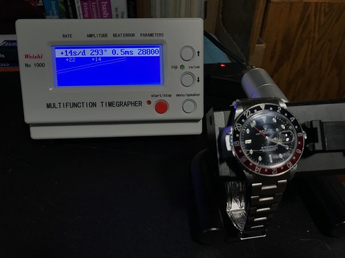
Here is a tool I have used to test mechanical watches: the Timegrapher. It has a sound transducer (a fancy name for a type of microphone) that listens to the ticking of a mechanical watch placed in its test fixture, compares it to its internal quartz oscillator, and displays the results.
I don't find any information about the quartz oscillator used in the my Timegrapher in its documentation. This is a common refrain when testing clocks. But any quartz oscillator - including the one in your quartz wristwatch, if you care to wear one - is likely to be far far better than the spring-driven mechanical movement in the Rolex GMT Master II shown above, and at a tiny fraction of the cost. The same cannot be said, alas, when comparing a quartz oscillator to a clock that is disciplined - that is, continually steered or adjusted - to a GPS reference.
Network Time Protocol
I currently have six small Network Time Protocol (NTP) servers on the local area network at the Palatial Overclock Estate. Two are commercial devices, and the rest are ones I designed and built myself. All but one are GPS-disciplined; the odd one out has an AM radio receiver it uses to pickup and decode the NIST WWVB time transmission. One of the GPS-disciplined servers I built has a cesium chip-scale atomic clock (CSAC) it uses as a frequency source.
Exactly how does one assess the accuracy and precision of a GPS-disciplined clock - especially one that incorporates a cesium atomic clock, a technology from which is currently derived the literal definition of the second - without having a clock that is even more accurate and precise?
That's the problem I continually face: any test instrument - like a digital oscilloscope - that I am able to afford, even one with an oven-controlled quartz oscillator (OCXO) or a temperature-compensated quartz oscillator (TCXO), either of which is far better than the quartz oscillator in my Timegrapher, is likely to be not nearly as good as the GPS-disciplined clock I built. If I try to measure the jitter (short term variation) or drift (long term variation) in my GPS-disciplined clock, am I measuring the error in the clock, or the error in the instrument?
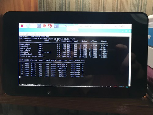
I addressed this problem with my NTP servers by building a little test system, Cesium, using open source NTP software. Cesium runs 24x7, and periodically requests the time from all of my NTP servers plus some public NTP servers on the Internet. The statistical tests in the NTP software score each server. I wrote about this in Monitoring GPS and NTP: Yet Another Raspberry Pi Project
What clock is Cesium using? It's Raspberry Pi has a 19.2MHz crystal oscillator (later Pi models use a 54MHz crystal oscillator). The Raspberry Pi oscillator is not temperature compensated, nor is it GPS-disciplined. And its frequency isn't the final word in how precise or accurate it is. This little tool is useful at a gross level, but it is in no way adequate for more rigorous testing.
UBX-ZED-F9T
This problem came to light again recently when I purchased a Sparkfun board with a U-blox ZED-F9T Global Navigation Satellite System (GNSS) receiver. When its antenna remains in a fixed position over a long period of time (like the window of my home office), so that the long term weighted average of its navigation solution has a low error, the F9T can act as a very accurate and precise time and frequency source. It bases its solution on an ensemble of satellites that are part of the U.S. GPS, Russian GLONASS, Chinese BeiDou, and European Galileo GNSS constellations.

The ZED-F9T is another example of the ninth generation of U-blox GNSS receivers, like the ones I have used in my Differential GNSS (DGNSS) projects that I wrote about in Practical Differential Geolocation. This receiver, though, is especially designed to be a time and frequency source. The SparkFun board is equipped with three SMA connectors: the center one is the input for the receiver's active multiband GNSS antenna, and the other two are outputs for software-configurable digital timing pulses.
Who doesn't need a GPS-disciplined time and frequency source? I decided to set up test bed using the ZED-F9T - ignoring the fact that I don't have a high-quality laboratory-calibrated oscilloscope (the cost of which could easily run into five or even six figures) - and see what I could see.
The documentation for the F9T say it can emit an output pulse with a frequency up to 25MHz. Although the internals of the F9T are proprietary, this is likely to be a performance limit of its baseband processor, which is probably has some kind of ARM core. The F9T (and in fact all GNSS receivers) has a broadband processor where the digital signal processing of the gigahertz GNSS signals is done, and a more conventional baseband processor where solution computations and input and output messaging is performed. F9T docs say that the device's real time clock (RTC) is driven by a 32KHz crystal oscillator, and suggest that it is not temperature compensated. The F9T's datasheet claims an output time pulse jitter of ±4 nanoseconds. The device is marketed as being suitable for stringent 5G cellular network timing.
I wrote a script, using my Hazer open source GNSS toolkit, to configure the F9T's first time pulse output to emit a 1Hz pulse, and its second time pulse output to emit a 10MHz pulse. 1Hz, a.k.a. one pulse per second (1PPS), is a commonly used mechanism to syntonize a time clock to GNSS time, while 10MHz is (as we will soon see) a commonly used frequency reference for test and measurement equipment.
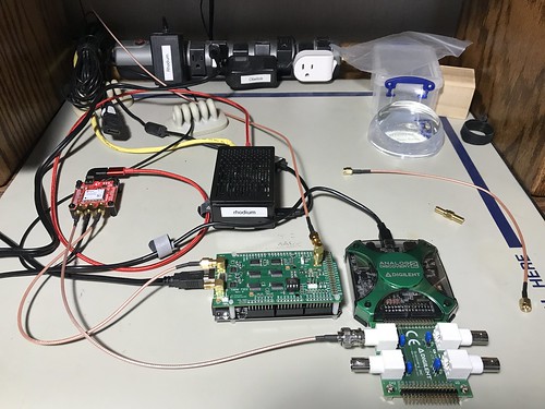
Arrayed next to the F9T on my workbench is Rhodium, a Raspberry Pi, and my modest test equipment (described below). The Pi is where my software runs. The Pi has a Universal Serial Bus (USB) connection to the F9T to provide power and a serial connection for configuration and monitoring.
TAPR TICC
The TAPR TICC is a time interval counter with claimed 60 picosecond resolution. It is produced by the Tucson Amateur Packet Radio (TAPR) organization. It consists of a specialized board mated to an Arduino Mega 2560. It has three SMA connectors: one for its reference clock input (more on that below), and two channels of input that it can timestamp, either in absolute or differential terms. It uses the Arduino USB connection for power, and as a serial connection for configuration and monitoring.
The TICC is a relatively low frequency (albeit high resolution) device, because it outputs a line of ASCII text for every pulse it detects. This makes it suitable for characterizing the 1PPS output of the F9T.
The TAPR TICC documentation has this to say about its timing capabilities.
The TAPR TICC is a two-channel timestamping counter with better than 60 picosecond resolution and less than 100 picosecond typical jitter. It has an Allan Deviation noise floor below 1e-10 for a one second measurement.The TICC requires an external 10 MHz reference clock at nominally +3 dBm.
The 10MHz reference clock required by the TICC was provided by a LeoNTP, one of my commercial GPS-disciplined NTP servers, manufactured by Leo Bodnar Electronics. I've had the LeoNTP on my home network for several years. It consistently scores well with my Cesium NTP monitoring tool. I also find its front-panel user interface easy to use. That's two of the reasons I chose it as my reference clock. Another is that it has a BNC connector with a 10MHz output for just this purpose.
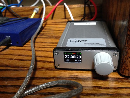
The docs for the LeoNTP has this to say about its timing accuracy and precision of its BNC time pulse output.
3.3V into High Impedance, 1.5V into 50Ohm PPS/1Mhz/10Mhz Accuracy 30ns RMS, 60ns 99%
While this isn't bad, you'll notice that it's not nearly as good as the claimed performance of the F9T. One of the applications I hope to use the F9T for is as a GPS-disciplined 10MHz reference clock for the TICC and other such devices.

This is a screen snapshot of the output of the TICC as it timestamps the 1PPS time pulses from the Z9T. You can see the difference between the time pulses are in generally the range of single digit nanoseconds. Given that its reference clock has a claimed precision that is about an order of magnitude worse than that of the Z9T, this is pretty good, although it's not clear whether I'm really measuring the Z9T, or the LeoNTP.
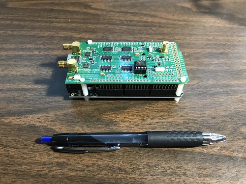
Digilent Analog Discovery 2
The Diligent Analog Discovery 2 is a recent generation USB oscilloscope. The device claims it can sample analog inputs 100 million times a second (100MS/s). Since the 10MHz (100ns wide) time pulse output of the Z9T generates 10MS/s, I had some hope that this handy tool would serve. (Long time readers will know that this is not my first USB oscilloscope. But it is the first one with this high a sampling rate.)
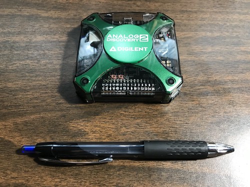
All the sampling and measurement hardware is in the little palm-sized pod, which is USB-connected to a host computer (a Lenovo laptop running Windows 10 in my case) for power and to provide the graphical display. The laptop runs Digilent's WaveForms software.
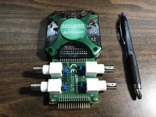
One great feature of the AD2 that sets it apart from other USB scopes is that it has an optional adaptor board for BNC connectors. This allows you to use conventional oscilloscope probes with it. Or, in my case, BNC-to-SMA cables.
Hint: if you buy an AD2, regardless of what you use it for, you really want the adaptor board. Depending on your application, you may also want to switch the blue jumper blocks, visible here on the adapter, from the AC pins - as shipped - to the DC pins. Failure to do so causes waveforms like the 1PPS time pulse to look really funky, as the underlying circuitry tries to remove the underlying DC component from the AC signal.
The AD2 documentation has some useful information about the device's clock generator, much of which is over my head.
A precision oscillator (IC31) generates a low jitter, 20 MHz clock.
The ADF4360-9 Clock Generator PLL with Integrated VCO is configured for generating a 200 MHz differential clock for the ADC and a 100 MHz single-ended clock for the DAC.Analog Devices ADIsimPLL software was used for designing the clock generator. The PLL filter is optimized for constant frequency (low Loop Bandwidth = 50 kHz and Phase Margin = 60°).
The Phase jitter using a brick wall filter (10.0 kHz to 100 kHz) is 0.04° rms.
The AD2 is capable of being both an oscilloscope and a wave form generator. I'm guessing the former uses the Analog-to-Digital Convertor (ADC), and the latter uses the Digital-to-Analog Convertor (DAC), mentioned above. (The AD2 can also be used as a digital logic analyzer, suitable for commonly used external interfaces on microcontrollers and embedded processors, like SPI, I2C, and UART.)
Low Frequency Events
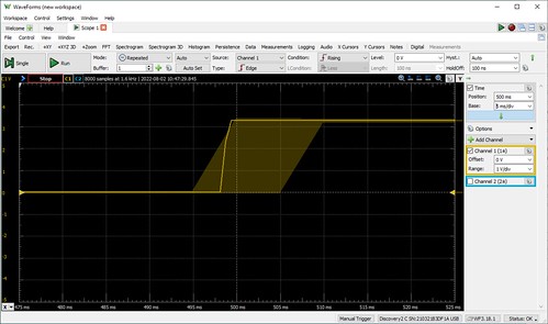
Pointing the AD2 at the 1PPS time pulse output of the F9T yielded the following wave form.

Once I collected some 1PPS output samples in the AD2, I used the software's built in capability to measure the period between two successive pulses.
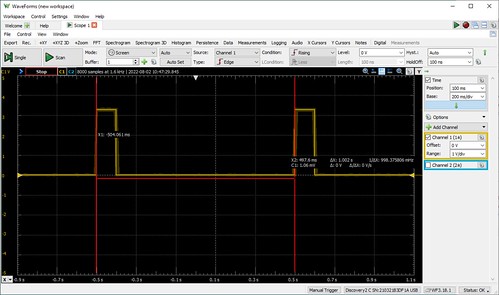
The AD2's measurement of the pulses being 1.002 seconds apart (a period equivalent to a frequency of about 9.98MHz) is not great, and not typical of the timing reported by the TICC. Once again, it's not clear I'm measuring the F9T, or the goodness of the AD2. But given the AD2's sampling rate of 100MHz, I would expect a measurement error of as much as ±10ns, once again not as good as the F9T's claimed ±4ns. (You're probably detecting a theme here.)
Cranking the display resolution up on the stored samples, in effect zooming in on the graph, the WaveForms tool shows what the docs say is a "noise band indicating glitch or higher frequency components than the sampling frequency". (It's not clear to me how the device knows anything about what's going on above its sampling frequency.)

Cranking the resolution a little higher shows a graph that indicates the actual points at which the 1PPS wave form was sampled. Now we can see some ground truth (which was probably already obvious to the hardware folks): the display consists of straight lines between successive sampling events. The rise of the 1PPS output line from ground to VDC (the 3.3V logic level of the F9T) cannot be instantaneous, and in fact is captured by the 100MHz sampling rate of the AD2. This explains the slight jog in the leading edge of some of the 1PPS pulses that is visible in the lower resolution displays. (This insight will be even more useful shortly.)
High(er) Frequency Events
Pointing the AD2 at the F9T's 10MHz time pulse output, we would expect see even more measurement artifacts, since the AD2's sampling rate is merely ten times the frequency of the signal we are measuring.
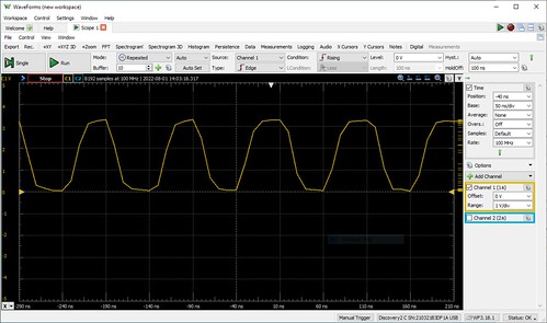
The 10MHz time pulse is a digital signal, but not a sine wave. But its visualization by the AD2, and the fact the output signal cannot change instantaneously, makes it look like one.
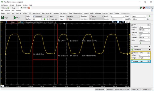
Measuring the period of the time pulse becomes even more challenging. At what point do we compare successive pulses? The TAPR TICC, for example, counts anything that rises above a threshold of 1.7V as a pulse. Doing so here gives us a frequency of about 9.83MHz.

It occurred to me that measuring at the point in the pulse where it starts to rise might be a better indication of the goodness of the F9T. Doing so gives us a frequency just barely short of 10MHz, off by a claimed 0.2ns, probably within the measurement error of the AD2, and certainly within the claimed precision of the F9T. (0.2ns is smaller than the period of the sampling rate, 10ns, so once again it's not clear to me how the instrument knows this.)
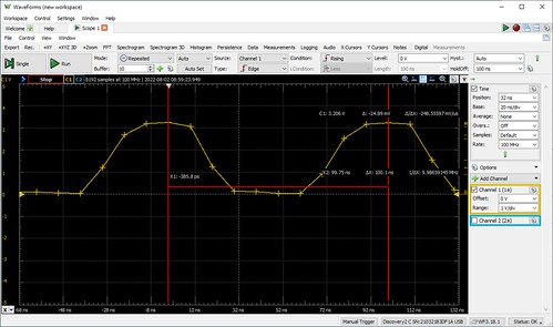
Cranking the display resolution a little higher shows us the AD2's sampling points on the 10MHz wave form. (It also shows us why the wave form is a little funky looking, as the straight lines between samples become more obvious.) We can more carefully choose the data points that we used to measure the interval between time pulses.

It occurs to me (again, probably obvious to the hardware folks) that how good the 10MHz output of the F9T appears will depend upon both the input impedance - effectively the speed at which the analog signal can change, due to the electrical characteristics of the circuit - and the measurement threshold (e.g. 1.7V?) of the device that is making use of it.
Conclusions
Neither TAPR TICC nor the Digilent Analog Discovery 2 are good (read: expensive) enough to really judge the quality of the output of the U-Blox ZED-F9T. I'll leave that to the folks with the $25,000 (or more) oscilloscopes with the oven-controlled quartz crystals. However, they were absolutely indispensable at debugging my configuration script for the F9T. Without them, I would have had no idea if I were even in the ball park with the fairly complex messaging my software was sending to the F9T. For no other reason than this, I recommend cost effective instruments like these for any embedded software developer's toolkit.
As for my own applications of the F9T, my opinion is: if it's good enough for 5G, it's probably good enough for me.


2 comments:
The LeoNTP also uses a Ublox module under the hood, which may explain the accuracy. Great devices, apart from the OLED burn-in, which is somewhat alleviated by the screen saver in newer firmware versions.
I agree! I wrote about my happiness with the LeoNTP way back in 2017 in "My Stratum-1 Desk Clock", https://coverclock.blogspot.com/2017/03/my-stratum-1-desk-clock.html, in which I talked about building my first tiny NTP server. My NTP monitoring tool typically chooses the LeoNTP as its preferred time source based on its own statistical tests. Thanks for the comment, Fazal!
Post a Comment