Such devices are not appropriate for the the kinds of precision timing applications I described in Engines of Time; my attempt to do so quickly revealed the latency and jitter that the serial-to-USB conversion introduces, and that is deadly to Network Time Protocol (NTP) applications. But GPS-over-USB devices are really useful for quickly cobbling together a geolocation application like I described in Better Never Than Late, or for determining the general time-of-day at least to the nearest second.
A quick search for "GPS USB" on Amazon.com reveals a pile of such devices (and lots of other stuff). Most are pretty inexpensive: a few tens of dollars, if that. This turned out to be really useful when I was working on Hazer, a simple little C library to parse NMEA GPS sentences. My tiny little company ended up buying a large assortment of these devices - ten in all, plus a few other more special purpose GPS devices that didn't have USB interfaces - allowing me to test Hazer against a broad range of of NMEA sentences. (There were a few surprises here and there.)
All of these devices emit ASCII data in a standard format described in the document NMEA 0183 Standard for Interfacing Marine Electronic Devices (version 4.10, NMEA 0183, National Marine Electronics Association, 2012-06). While NMEA charges a hefty fee (hundreds of dollars) for the document, summaries are available for the price of a little web search fu. Typical NMEA output looks like this.
$GPRMC,213605.000,A,3947.6533,N,10509.2018,W,0.01,136.40,150217,,,D*77\r\n
$GPRMC,213605.000,A,3947.6533,N,10509.2018,W,0.01,136.40,150217,,,D*77\r\n
$GPGGA,213606.000,3947.6533,N,10509.2018,W,2,10,1.0,1710.9,M,-20.8,M,3.0,0000*75\r\n
$GPGGA,213606.000,3947.6533,N,10509.2018,W,2,10,1.0,1710.9,M,-20.8,M,3.0,0000*75\r\n
$GPGSA,M,3,23,16,09,07,26,03,27,22,08,51,,,1.9,1.0,1.6*36\r\n
$GPGSA,M,3,23,16,09,07,26,03,27,22,08,51,,,1.9,1.0,1.6*36\r\n
$GPGSV,3,1,10,23,86,091,32,16,58,058,39,09,50,311,38,07,32,274,22*72\r\n
$GPGSV,3,1,10,23,86,091,32,16,58,058,39,09,50,311,38,07,32,274,22*72\r\n
$GPGSV,3,2,10,26,30,046,32,03,26,196,39,27,24,120,41,22,13,183,43*74\r\n
$GPGSV,3,2,10,26,30,046,32,03,26,196,39,27,24,120,41,22,13,183,43*74\r\n
$GPGSV,3,3,10,08,10,155,34,51,43,183,43*79\r\n
$GPGSV,3,3,10,08,10,155,34,51,43,183,43*79\r\n
Because all the NMEA output is in ASCII, and the devices manifest as serial devices, you can play with them using your favorite terminal program, like screen for MacOS or Linux, or PuTTY on Windows.
Each sentence begins with a dollar sign and is terminated by an asterisk, with a simple checksum like 77, and carriage return/line feed pair. The NMEA application - GPS in this case, since there are other devices that emit other kinds of NMEA data - is identified with a GP, and its specific content by another token like, here, RMC, GGA, and GSV. Different sentences carrying different payloads, like the time of day in Universal Coordinated Time (UTC), current position in latitude and longitude expressed in degrees and decimal minutes, from exactly which satellites the position fix was derived, and the computed error in that position fix based on the orbital position of those satellites.
Why did I write Hazer to parse NMEA GPS sentences when there is plenty of perfectly usable open source code to do just that? In fact, I've used the most excellent open source GPS Daemon (gpsd) in all of my precision timing projects, as described in various articles like My WWVB Radio Clock. But as I'm fond of saying, I only learn by doing, and my goal with Hazer was to learn how NMEA GPS sentences were encoded. That turned out to be unexpectedly useful, as I've used what I've learned, and sometimes used Hazer itself, in a number of other projects, including one where I used gpsd as well.
All of the inexpensive GPS USB devices that I tested with Hazer use one of the following GPS chipsets.
- Quectel L80-R
- SiRF Star II
- SiRF Star III
- SiRF Star IV
- U-Blox 6
- U-Blox 7
- U-Blox 8
- Cygnal Integrated Products
- FTDI
- Prolific
- U-Blox (integrated into the GPS chip itself)
Most of these devices have an integrated patch antenna. As you will see in the photographs, a few required a separate amplified antenna in which the power was carried in-band over the coxial connection.
I didn't test the accuracy of any of these devices. But since they are all based on the a relatively small number of commercial GPS chipsets, a little web searching will yield useful information. All of these devices produced standard ASCII NMEA sentences that were easily usable by Hazer.
(Update 2019-11-25) I've tested all of the GPS/GNSS receivers shown in this article with my own software. The hosts used for testing vary widely depending on the application. They are all listed in the README for the Hazer repository.
Below is a list of the GPS USB devices, plus some others with other interfaces, that I used to test Hazer. For each, where possible, I identify the GPS chipset, the serial chipset, how often they generate an updated location, and some useful information regarding how to interface the device to a test system. If you are using any of these devices, or are trying to decide which to purchase, you may find this information useful.
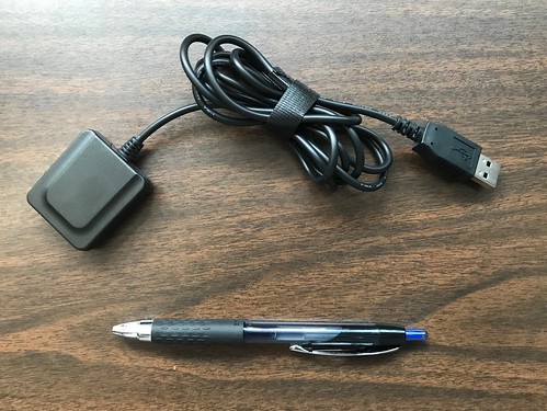
This is an excellent unit for everyday general-purpose geolocation use. It is relatively inexpensive and easily available from a variety of outlets. This device's slower baud rate - 4800 baud - is actually an advantage for applications that integrate it with the real-time GPS feature of Google Maps Pro. (Updated 2018-08-27: the name of this company appears to have changed recently from USGlobalSat to GlobalSat.)
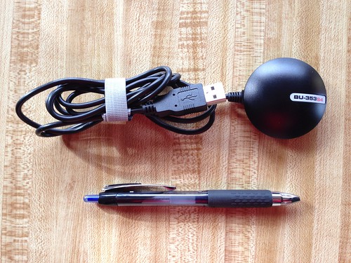
GPS chipset: SiRF Star IV
Serial chipset: Prolific
Serial parameters: 4800 8N1
udev Vendor/Product id: v067Bp2303
Device name: ttyUSB
Update frequency: 1Hz
USGlobalSat ND-105C
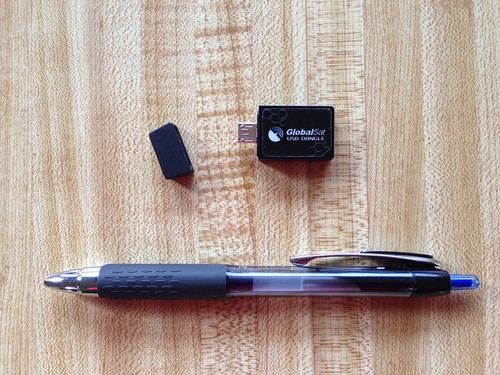
Serial chipset: Prolific
Serial parameters: 4800 8N1
udev Vendor/Product id: v067Bp2303
Device name: ttyUSB
Update frequency: 1Hz
USGlobalSat BU-353S4-5Hz
Like the other similar USGlobalSat unit but with a higher sentence frequency. (2018-08-27: the name of this company appears to have changed recently to from USGlobalSat to GlobalSat.)
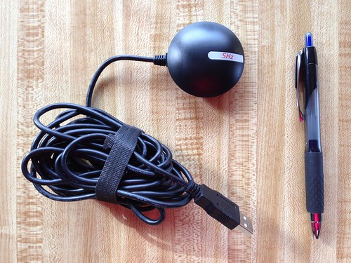
Serial chipset: Prolific
Serial parameters: 115200 8N1
udev Vendor/Product id: v067Bp2303
Device name: ttyUSB
Update frequency: 5Hz
Stratux Vk-162 Gmouse
Serial chipset: integrated
Serial parameters: 9600 8N1
udev Vendor/Product id: v1546p01A7
Device name: ttyACM
Update frequency: 1Hz
Eleduino Gmouse
Serial chipset: integrated
Serial parameters: 9600 8N1
udev Vendor/Product id: v1546p01A7
Device name: ttyACM
Update frequency: 1Hz
Generic Gmouse
(That is how it was listed on Amazon.com.)
Serial chipset: integrated
Serial parameters: 9600 8N1
udev Vendor/Product id: v1546p01A7
Device name: ttyACM
Update frequency: 1Hz
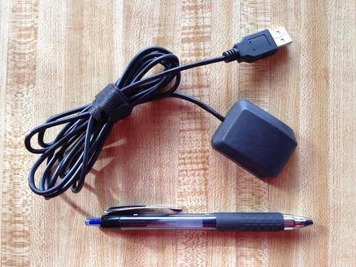
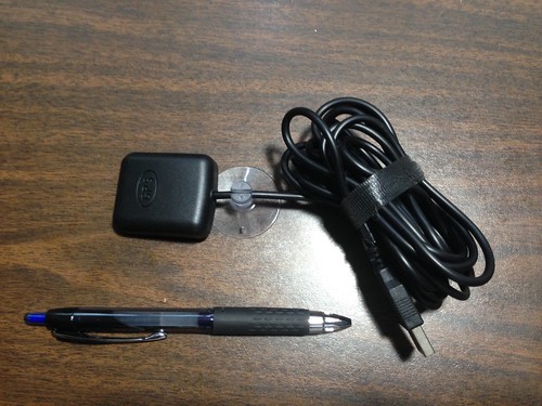
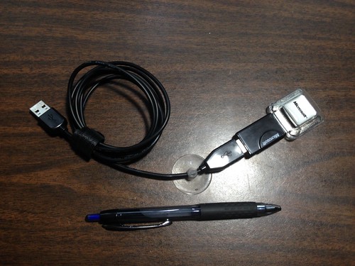
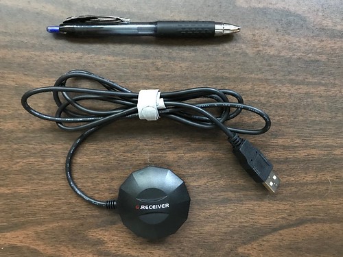
Pharos GPS-360
Serial chipset: Prolific (likely integrated into provided cable)
Serial parameters: 4800 8N1
udev Vendor/Product id: v067BpAAA0
Device name: ttyUSB
Update frequency: 1Hz
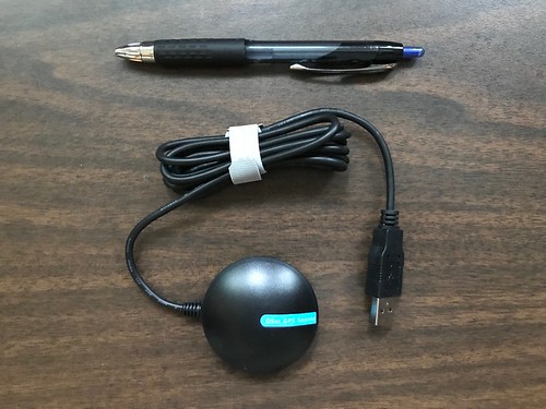
Pharos GPS-500
GPS chipset: SiRF Star III
Serial chipset: Prolific (likely in provided dongle)
Serial parameters: 4800 8N1
udev Vendor/Product id: v067BpAAA0
Device name: ttyUSB
Update frequency: 1Hz
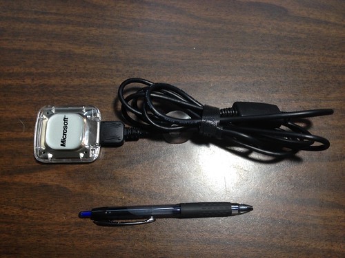
MakerFocus USB-Port-GPS
Shown attached to a Raspberry Pi as part of a larger project in which I integrated Hazer with Google Earth to create a moving map display. Supports 1PPS over a digital output pin.
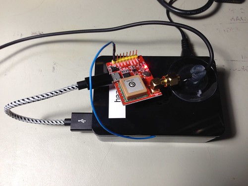
GPS chipset: Quectel L80-R
Serial chipset: Cygnal (based on Vendor ID)
Serial parameters: 9600 8N1
udev Vendor/Product id: v10C4pEA60
Device name: ttyUSB
Update frequency: 1Hz
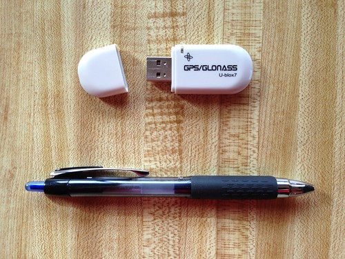
Sourcingbay GM1-86
GPS chipset: U-Blox 7
Serial chipset: probably integrated
Serial parameters: 9600 8N1
udev Vendor/Product id: p1546v01A7
Device name: ttyACM
Update frequency: 1Hz
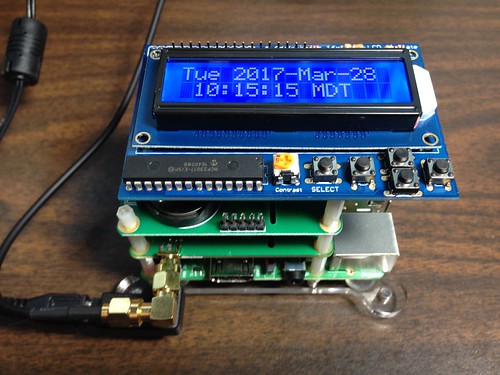
Shown in a Raspberry Pi stack as part of Hourglass, a GPS-disciplined NTP server; it's the board with the SMA connector extending out the bottom to which a coaxial cable to an active antenna is attached.
Serial chipset: N/A (logic-level serial)
Serial parameters: 9600 8N1
udev Vendor/Product id: N/A
Device name: ttyAMA
Update frequency: 1Hz
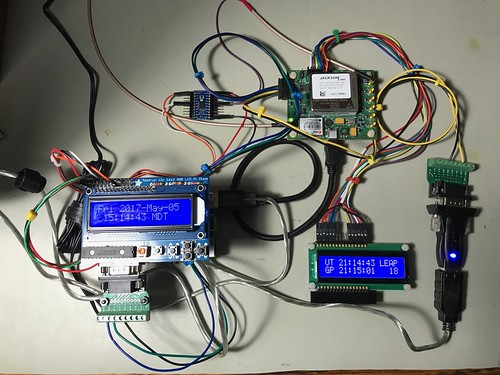
Jackson Labs Technologies CSAC GPSDO
This is a breathtakingly expensive part, shown upper right as part of Astrolabe, an NTP server with a GPS-disciplined oscillator (GPSDO) that includes a cesium chip-scale atomic clock (CSAC).
Serial chipset: N/A (RS232 serial)
Serial parameters: 115200 8N1
udev Vendor/Product id: N/A
Device name: ttyACM
Update frequency: 1Hz
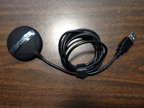
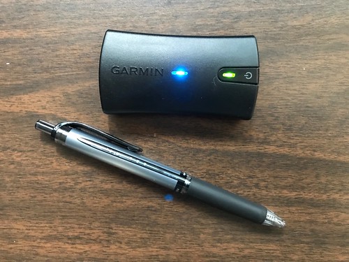
Garmin GLO
Purchased for and works well with Android GPS applications like the ones I routinely use with my Google Pixel C Android tablet.
Serial chipset: N/A (Bluetooth)
Serial parameters: N/A
udev Vendor/Product id: N/A
Device name: rfcomm
Update frequency: 10Hz
NaviSys Technology GR-701W (added 2018-05-04)
Supports a One Pulse Per Second (1PPS) signal by asserting DCD on the simulated serial port. Receives WAAS augmentation too. Can be used to build small GPS-disciplined NTP servers like Candleclock. The USB interface jitters the timing enough that it's my least precise NTP server, but it is still better than no local NTP server at all. It's available on Etsy.
GPS chipset: U-Blox 7
Serial chipset: Prolific
Serial parameters: 9600 8N1
dev Vendor/Product id: v067Bp2303
Device name: ttyUSB
Update frequency: 1Hz
TOPGNSS GN-803G (added 2018-08-08)
Has multiple RF stages so that it can receive more than one GNSS frequency at a time. Supports GPS, QZSS, GLONASS, and BEIDOU. By default, receives GPS and GLONASS and computes ensemble fixes. Supports WAAS, EGNOS, MSAS. Has seventy-two channels. A remarkable device for its price.
GPS chipset: U-Blox 8 (UBX-M8030-KT)
Serial chipset: U-Blox 8
Serial parameters: 9600 8N1
dev Vendor/Product id: v1546p01A8
Device name: ttyACM
Update frequency: 1Hz
GlobalSat BU-353W10 (added 2018-08-27)
Like the GN-803G above, this device uses the U-Blox 8 chipset, and so it has the multiple RF stages and computes ensemble fixes using GPS and GLONASS plus WAAS. It's a few dollars more than the GN-803G, but is available from Amazon.com with two-day shipping, where as I ordered the GN-803G from eBay and it was shipped from China. One interesting difference is that the GN-803G updates the satellite view (via NMEA GSV sentences) once per second, but the BU-353W10 updates the view every five seconds; the position fix and list of active satellite is still updated once a second. Since this device has advanced features I crave, and is easily acquired, it will likely be my go-to USB GPS device going forward (unless I need special features it doesn't have, like 1PPS).
GPS chipset: U-Blox 8 (UBX-M8030)
Serial chipset: U-Blox 8
Serial parameters: 9600 8N1
dev Vendor/Product id: v1546p01A8
Device name: ttyACM
Update frequency: 1Hz
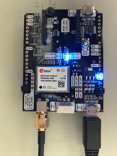
Ardusimple SimpleRTK2B (updated 2019-02-24)
The SimpleRTK2B is an Arduino-compatible shield which can be used standalone, as I have done below, without headers through its USB-to-serial interface which also provides power. The SimpleRTK2B is based on the U-Blox ZED-F9P chip. This U-Blox 9 chip is remarkable in that it has all the goodness of the U-Blox 8, but also has the RF hardware and decode capability to receive not only GPS (U.S.) and GLONASS (Russia) signals, but also Galileo (E.U.) and Beidou (China). And it trivially does so, without any work on my part. Right out of the box, it computes an ensemble fix based on pseudo-ranges from all four constellations, and tries to use at least four satellites when possible from each constellation to do so. I suspect this makes it much more resistant to jamming and spoofing.
The device also supports Real-Time Kinematics (RTK), where two GPS receivers exchange information in the form of Radio Technical Commission for Maritime services (RTCM) messages, allowing built-in algorithms to potentially compute much more precise position fixes.
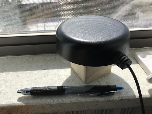
To receive signals from the four different constellations requires a multiband active antenna. The one I used is about the size of a hockey puck.
GPS chipset: U-Blox 9 (ZED-F9P)
Serial chipset: U-Blox 9
Serial parameters: 38400 8N1
dev Vendor/Product id: v1546p01A9
Device name: ttyACM
Update frequency: 1Hz
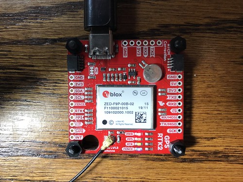
SparkFun GPS-RTK2 (updated 2019-07-12, 2019-11-25)
This is SparkFun's take on the same U-Blox 9 chip as is used in the Ardusimple SimpleRTK2B board. It lacks the Digi radio integration (which I ended up not using anyway). It has a USB-C port instead of a micro-B port. It provides a lithium battery to maintain memory on the receiver which might improve your chances of doing a hot start. Also, it ships from Boulder Colorado - a half hour or so drive from me - instead of from Barcelona Spain. So far it seems to function identically with Hazer, and its sister projects Yodel and Tumbleweed, as the SimpleRTK2B.
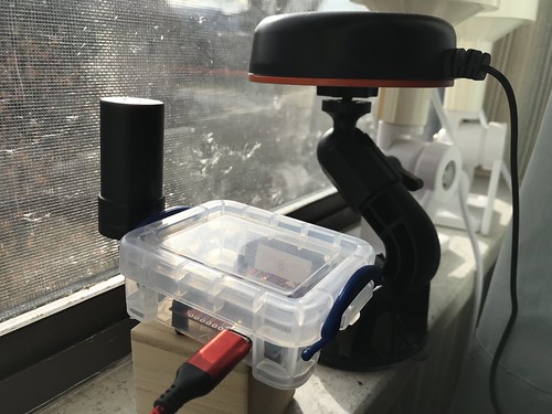
Below is a GPS-RTK2 board in an improvised case (a tiny 0.07 liter Really Useful Box from the office supply store; I've also used the 0.14 liter version), with a helical multi band active antenna. I used a Dremel tool to make holes for the USB connector, the antenna connector, and to mount the board to the bottom of the case using nylon standoffs. Side by side testing has shown the helical antenna to be less sensitive to weak signals than others I've used, but it is supposed to be less dependent on physical orientation (good for applications like drones).

Below is the GPS-RTK2 with the helical antenna in the window of my home office. Behind it is the hockey puck GNSS antenna mentioned above on a gimbaled camera mount with a steel ground plate (painted orange), and behind that, two marine GPS antennas. (When I took this photograph I had a total of eight GPS/GNSS antennas in my window, each connected to an active receiver.)
GPS chipset: U-Blox 9 (ZED-F9P)
Serial chipset: U-Blox 9
Serial parameters: 38400 8N1
dev Vendor/Product id: v1546p01A9
Device name: ttyACM
Update frequency: 1Hz
Software Defined Radio (updated 2019-02-05)
If you had any doubt as to the amazing capabilities of devices like the GlobalSat BU-353W10 GPS USB dongle described above - or any other consumer device that uses the Ublox 8 chipset - try duplicating it using a software defined radio (SDR) and open source software. My experience is I can get a small fraction of the performance of that US$40 device for about one hundred times its price and many
For sure your mileage may vary. My experience in this domain (which was hard won for me, not being a radio frequency guy, nor a signal processing guy, nor even a hardware guy) was that the performance of the GPS SDR depends on a bunch of environmental factors over which I have little or no control, like the weather (snowing == bad), or even time of day (sun == bad). After a long expensive learning experience, I am sometimes - but with no consistency or reliability - able to get a position fix. It is entirely possible that with more learning and less ignorance on my part, this setup could work a lot better. This is definitely a work in progress, although it is progressing very slowly.
Here's a photograph of my hardware.
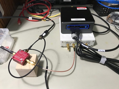
After several false starts, I ended up using the Ettus Research B210 Universal Software Radio Peripheral (USRP). The B210 has a 12-bit analog to digital convertor - cheaper units use an 8-bit ADC - which I found was important for the SDR to be able to discriminate the GPS signals, which are so weak as to be barely detectable from the background radio noise. It has a USB 3.0 interface, which has been useful for the system to keep up with the fire hose of data from the B210. The B210 can be completely bus powered over the USB cable, which will be useful when I truck this around the neighborhood, as I am prone to do. I also opted to equip my B210 with an optional GPS-disciplined oscillator (GPSDO), that includes a temperature compensated crystal oscillator (TCXO), to use as a precision frequency source. That means I had to provide two GPS antennas, one for my GPS SDR, and one for the hardware GPS receiver. The irony of using a hardware GPS receiver to implement a software GPS receiver is not lost on me. The B210 is the cream colored box with the SMA connectors in the photograph above.
The B210 doesn't provide a bias tee (some radios do), a device that allows you to provide power over the coaxial cable to a GPS antenna that contains active elements in the form of a low noise amplifier. An LNA is necessary to boost the signals, which can be so weak as to be defeated just by the loss over the coax cable between the antenna and the radio. I tried several different bias tees (they aren't expensive, relatively speaking) before I settled on the little red device in the photograph, a CrysTek Microwave CBTEE-01-50-6000. I broke out my soldering iron to hand-fabricate the USB-to-SMA cable that powers the bias tee. (Update 2019-02-04: I've been trying other bias tees since then.)
The window of my home office now has eight GPS antennas sitting on the sill. Here are the two I used for my SDR.
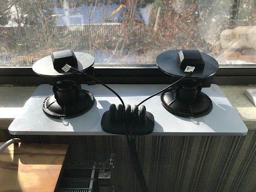
I used two active 5V GPS antennas. I lovingly hand-crafted the dual setup (one for the SDR, one for the GPSDO) using two camera-tripod-style gimbaled mounts. Each mount has a ground plane, a conducting surface - here, a hunk of steel weighting about a quarter pound each - that has a radius of at least a quarter of a wavelength. The ground plane simulates the earth ground and serves to reflect the radio waves back into the antenna. I have no clue how necessary these are, but they were just a few bucks each.
The code name for this project is "Critter" and the repository containing the scripts and configuration files I used to implement it can be found on GitHub.
# gnss-sdr --config_file=../etc/gnss-b210-a.conf --log_dir=.
to run my GPS SDR, using a GNSS-SDR configuration file (update: whose name has since changed) that can be found in the repository for my project code-named Critter. Below is the output of one of my successful attempts.
NAV Message: received subframe 5 from satellite GPS PRN 31 (Block IIR-M)
NAV Message: received subframe 5 from satellite GPS PRN 32 (Block IIF)
NAV Message: received subframe 5 from satellite GPS PRN 10 (Block IIF)
Current input signal time = 125 [s]
Current input signal time = 126 [s]
Current input signal time = 127 [s]
Current input signal time = 128 [s]
Current input signal time = 129 [s]
Current input signal time = 130 [s]
NAV Message: received subframe 1 from satellite GPS PRN 31 (Block IIR-M)
NAV Message: received subframe 1 from satellite GPS PRN 32 (Block IIF)
NAV Message: received subframe 1 from satellite GPS PRN 18 (Block IIR)
NAV Message: received subframe 1 from satellite GPS PRN 10 (Block IIF)
Current input signal time = 131 [s]
First position fix at 2018-Dec-28 18:41:19 UTC is Lat = 39.7941 [deg], Long = -105.153 [deg], Height= 1713.42 [m]
The RINEX Navigation file header has been updated with UTC and IONO info.
Position at 2018-Dec-28 18:41:19 UTC is Lat = 39.7942 [deg], Long = -105.153 [deg], Height= 1693.18 [m]
Current input signal time = 132 [s]
Position at 2018-Dec-28 18:41:19 UTC is Lat = 39.7942 [deg], Long = -105.153 [deg], Height= 1704.55 [m]
Current input signal time = 133 [s]
Position at 2018-Dec-28 18:41:21 UTC is Lat = 39.7942 [deg], Long = -105.153 [deg], Height= 1695.15 [m]
Current input signal time = 134 [s]
Position at 2018-Dec-28 18:41:21 UTC is Lat = 39.7942 [deg], Long = -105.153 [deg], Height= 1701.38 [m]
Position at 2018-Dec-28 18:41:22 UTC is Lat = 39.7942 [deg], Long = -105.153 [deg], Height= 1691.93 [m]
Current input signal time = 135 [s]
Position at 2018-Dec-28 18:41:22 UTC is Lat = 39.7941 [deg], Long = -105.153 [deg], Height= 1703.32 [m]
Position at 2018-Dec-28 18:41:23 UTC is Lat = 39.7942 [deg], Long = -105.153 [deg], Height= 1682.33 [m]
Current input signal time = 136 [s]
Position at 2018-Dec-28 18:41:23 UTC is Lat = 39.7942 [deg], Long = -105.153 [deg], Height= 1698.72 [m]
Once a position fix is achieved, the GNSS-SDR software generates NMEA sentences just like a conventional GPS receiver.
$GPRMC,184122.000,A,3947.6500,N,1059.2073,W,0.00,0.00,281218,,*2c
$GPGGA,184122.000,3947.6541,N,1059.2074,W,1,04,1.9,1690.0,M,0.0,M,0.0,0000*5d
$GPGSA,M,3,10,18,31,32,,,,,,,,,5.0,1.9,4.6*3a
$GPGSV,1,1,04,10,33,120,42,18,46,253,40,31,61,178,45,32,55,047,41*7f
$GPRMC,184122.000,A,3947.6501,N,1059.2070,W,0.00,0.00,281218,,*2e
$GPGGA,184122.000,3947.6507,N,1059.2066,W,1,04,1.9,1691.9,M,0.0,M,0.0,0000*54
$GPGSA,M,3,10,18,31,32,,,,,,,,,5.0,1.9,4.6*3a
$GPGSV,1,1,04,10,33,120,42,18,46,253,39,31,61,178,44,32,55,047,41*70
$GPRMC,184122.000,A,3947.6504,N,1059.2074,W,0.00,0.00,281218,,*2f
$GPGGA,184122.000,3947.6513,N,1059.2106,W,1,04,1.9,1679.1,M,0.0,M,0.0,0000*58
$GPGSA,M,3,10,18,31,32,,,,,,,,,5.0,1.9,4.6*3a
$GPGSV,1,1,04,10,33,120,42,18,46,253,38,31,61,178,45,32,55,047,41*70
$GPRMC,184122.000,A,3947.6502,N,1059.2079,W,0.00,0.00,281218,,*24
$GPGGA,184122.000,3947.6466,N,1059.2070,W,1,04,1.9,1689.5,M,0.0,M,0.0,0000*50
$GPGSA,M,3,10,18,31,32,,,,,,,,,5.0,1.9,4.6*3a
$GPGSV,1,1,04,10,33,120,42,18,46,253,41,31,61,178,45,32,55,047,43*7c
After sometimes waiting as long as twenty minutes for the SDR to acquire and track the minimum of four satellites necessary for a position fix and receiving the required navigational messages, I got the real-time report from gpstool
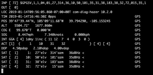
by piping the NMEA output into Hazer's gpstool
$ tail -f gnss_sdr_pvt.nmea | gpstool -E
which updated sporadically as the SDR had to acquire different satellites as they moved in their orbits. (You can tell from the timestamps that this was a different attempt from the one above.)
Below is a screen sweep of the commands I use to report all of the versions of the software and firmware.
# uname -a
Linux cadmium 4.15.0-43-generic #46~16.04.1-Ubuntu SMP Fri Dec 7 13:31:08 UTC 2018 x86_64 x86_64 x86_64 GNU/Linux
# lsb_release -a
No LSB modules are available.
Distributor ID: Ubuntu
Description: Ubuntu 16.04.5 LTS
Release: 16.04
Codename: xenial
# gnuradio-config-info --version
3.7.13.4
# gnss-sdr --version
gnss-sdr version 0.0.10
# uhd_find_devices
[INFO] [UHD] linux; GNU C++ version 5.4.0 20160609; Boost_105800; UHD_3.14.0.0-0-gd20a7ae2
--------------------------------------------------
-- UHD Device 0
--------------------------------------------------
Device Address:
serial: 31736DE
name: MyB210
product: B210
type: b200
If, like me, you are interested in the finer details of how GPS works, this might be the setup for you. Just don't kid yourself. For just a few thousand dollars I am confident that you too can sometimes partially duplicate a fraction of the functionality and none of the reliability of a forty dollar USB dongle you can order from Amazon.com.
GPS chipset: SDR (USRP B210, GNURadio, GNSS-SDR)
Serial chipset: N/A
Serial parameters: N/A
udev Vendor/Product id: v2500p0020
Device name: N/A
Update frequency: sporadic


5 comments:
You might also see if you can scrounge up a Navisys GR-601W / 701W / 801W, which delivers 1PPS from the GPS to DCD over the serial-to-USB adapter:
Specs:
http://www.navisys.com.tw/products/GPS&GNSS_receivers/flyer/GR-701_flyer-150703.pdf
Origin:
http://esr.ibiblio.org/?p=4281
http://esr.ibiblio.org/?p=4335
You talked me into it. I ordered one. We'll see what she does.
Thanks for the tip, Royce. I got the GR-701W. I updated Diminuto to be able to detect when DCD is asserted, and gpstool in Hazer to optionally use it. The GR-701W (the W specifically supports DCD for 1PPS) does indeed seem to toggle DCD and appears to do so in sync with my nearby GPS clock (within human perception anyway). I don't know when or if I might build a fourth clock using this device, but I would expect gpsd (which also supports DCD) to deal with it. Thanks again!
Hii Guys..
I see your blog, your blog is very impressive. and it is very useful for my project. I have more Details of this GPS Antenna. Click below.
GPS Antenna
GNSS receivers with NMEA output are valuable tools for geolocation and general timing applications. While not suitable for high-precision timing due to USB-induced latency, they are affordable and versatile for various projects. Understanding the NMEA output format and the specifics of different devices can greatly aid in their effective use.
GPS Antenna Manufacturers
Post a Comment