While Hazer's gpstool utility supports a wide variety of GPS/GNSS receivers, the one I chose for the test fixture is a SparkFun board equipped with a u-blox NEO M9N device. Here is some gpstool output generated while exercising the M9N.

I chose the M9N because it can receive and process transmissions from the satellite constellations of the U.S. GPS (a.k.a. NAVSTAR) system, the Russian GLONASS system, the European Galileo system, and the Chinese BeiDou 2 (a.k.a. COMPASS) system simultaneously. This tests more code paths in the underlying Hazer library and in gpstool.

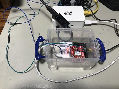
The M9N is powered by a USB C connection to a dedicated Raspberry Pi 4B running Raspberry Pi OS, the Debian-based version of GNU/Linux formerly known as Raspbian. The USB connection is also the serial communications channel between the Pi and the M9N. The Pi runs headless; when necessary, I ssh into it from my desktop Mac and use the command line interface (although in a pinch, I have connected up a display, keyboard, and mouse to the Pi, or even attached a USB-to-serial adapter to its console port pins).

You can see the SMA Radio Frequency (RF) connector emerging from the container, where it connects to the coaxial cable of the GNSS antenna used by the M9N. The small multi-band active patch antenna sits on the top shelf of my workbench within view of the window.

You can also see a green wire and a blue wire that run from the M9N container to the Raspberry Pi.
The green wire connects the 1PPS ("one pulse per second") signal from the M9N to a General Purpose Input/Output (GPIO) pin on the Raspberry Pi. 1PPS is a standard precision timing signal derived from the GNSS solution by the receiver (although not all of them export it, and when they do, the mechanism varies). I make use of 1PPS in all of my GNSS-disciplined Network Time Protocol (NTP) micro servers that I've written about previously, including the one that incorporates a chip-scale cesium atomic clock. When gpstool is configured to monitor the 1PPS signal, it uses Diminuto's GPIO feature to interrogate the input GPIO pin using the select(2) system call inside a dedicated POSIX thread (which is also a Diminuto feature).
The blue wire connects an second, output, GPIO pin on the Raspberry Pi to an LED in the little container where the M9N is mounted. When gpstool monitors 1PPS, it can be configured for the thread to strobe the second GPIO pin to follow the 1PPS signal. This is not just a test of Hazer and gpstool, but a test of Diminuto's GPIO feature as well.

My hardware engineer colleagues will confirm that I'm not a hardware guy by any stretch of the imagination. But hacking together these little hardware test fixtures gives me peace of mind. As long as I see that LED blinking at 1Hz, I know that, while my code is not perfect, it is at least sane.


No comments:
Post a Comment